3D Map with UI markers - Project setup & displaying markers (part 1)
2/13/2025
Martin Bozhilov
Overview
In this tutorial series, we’ll use Unreal Engine v5.4 and blueprints to design a 3D map level. The map will consist of UI elements (such as points of interest and area markers) that are dynamically moved on the HUD based on the location of in-game objects. Additionally, the points of interest will be hoverable and will display a tooltip with information about the location.
This tutorial will be split into two parts. In this part, we will focus on displaying the map markers on the map. In the second part, we will implement interaction features such as showing a tooltip when a POI element is hovered over by the mouse.
For the UI, we will use Gameface’s native and UE data-binding features to bind game data to the UI.
Resources
Project Initialization - Unreal Engine
We’ll begin by setting up the project in Unreal Engine. Use the getting started guide from our documentation to install the Gameface plugin and integrate it into an existing project or use the sample project created by the installer.
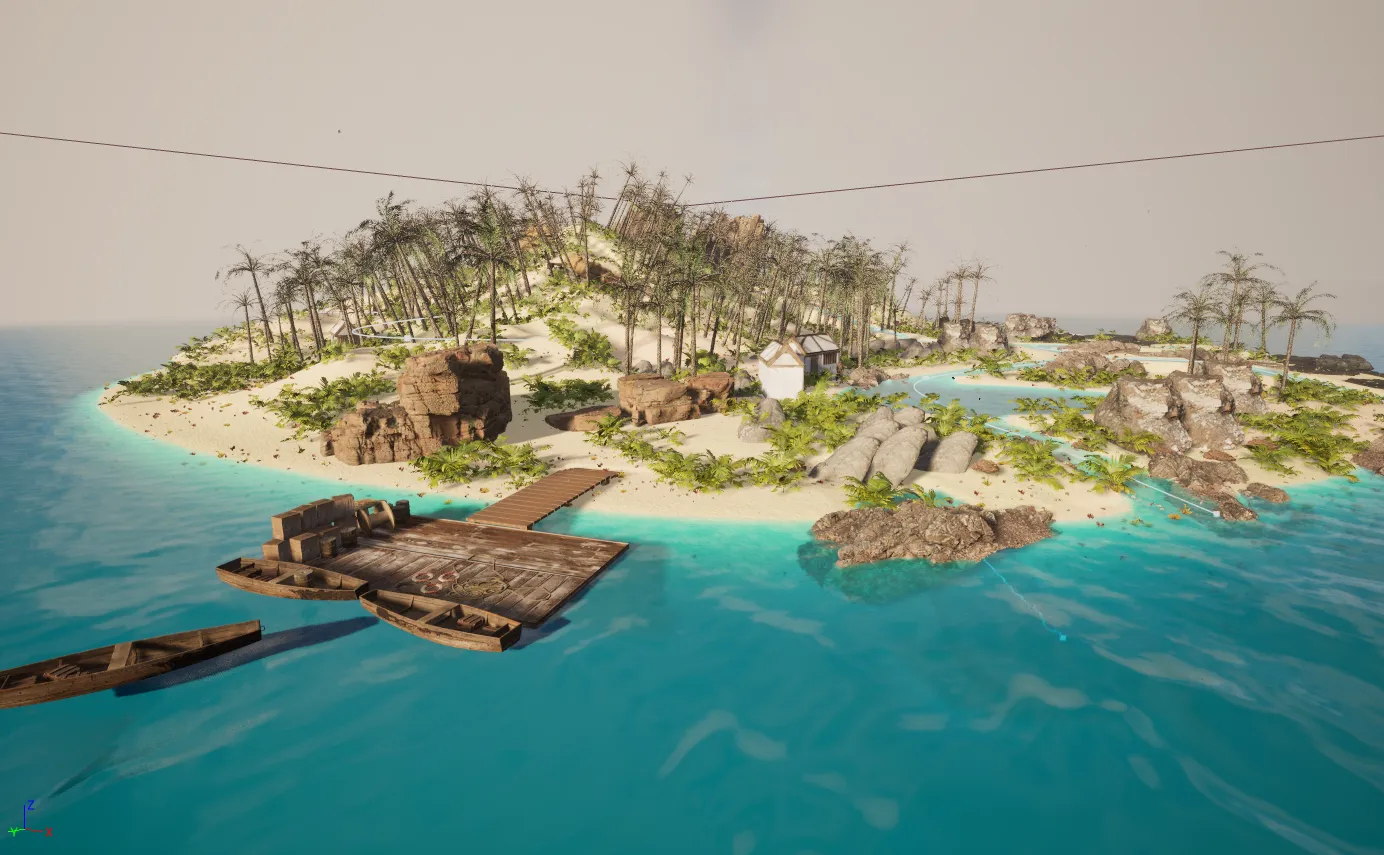
After that’s done, you can create your 3D level. In this tutorial, we are going for a pirate game theme, and our map will be a deserted island.
Setting Up Player Movement
The first step is to set up the movement of the player. For our project, we followed:
- Strategy Game Controller tutorial to set up the pawn actor and the camera movement logic
- WASD Camera Movement tutorial for the zoom logic.
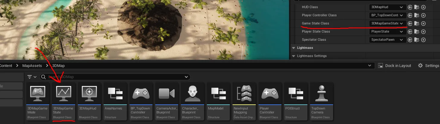
After following the tutorials, create a Game State Blueprint and add it to the Game Mode of our level.
The major part of our logic will be handled and managed by the Game State Blueprint. In our case, we named it 3DMapGameState.
Placing Actors for POIs and Area Markers
The next major task is to extract the data from the game objects to use it in the UI.
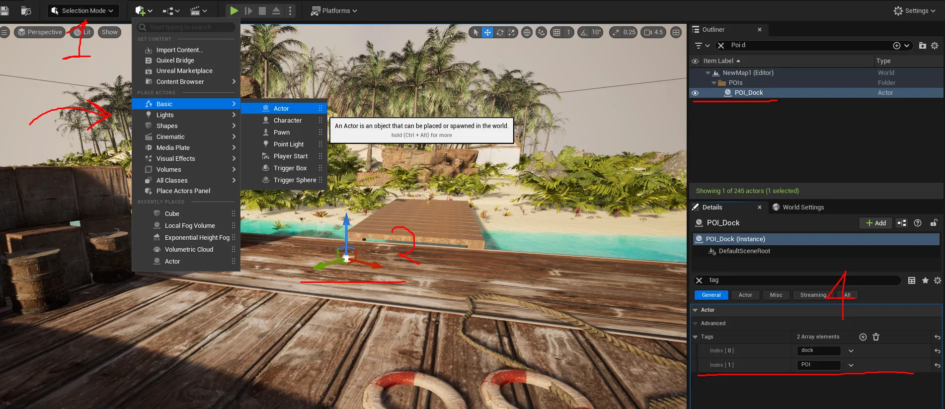
We took the approach of placing Actors in our world, on top of our points of interest (enemies, treasure chests, etc.), which actors we will get the world position of
to accurately place our UI elements.
After creating and placing the actors, we must label them for easy access. We are going to place 2 entries in the Tags array:
- Element with index 0 will be the name of the POI (dock, enemy, treasure) which we will show in our UI when the POI is hovered.
- Element 1 will be used to get all actors and manipulate them with the
Get All Actors of Class with TagBlueprint node.
When that is done, we are going to do the same for our area markers.
Data-Bind Model setup
Before we begin setting up any blueprint logic, we must set up our model which we will use in the UI - as it plays a very central role in our project.
To achieve this, we must do the following:
- Create
structuresfor the points of interest, the area names, and the model itself. - In the
GameStateblueprint, create variables that will hold the state and update the model dynamically. - On
Event Tick, update the model with the correct position of our elements relative to the screen. - Send these changes to the UI with
data-binding.
Creating the Structures
For this map UI, we are going to have 2 main UI elements - points of interest (POI) and area markers. Let’s create structs for both.
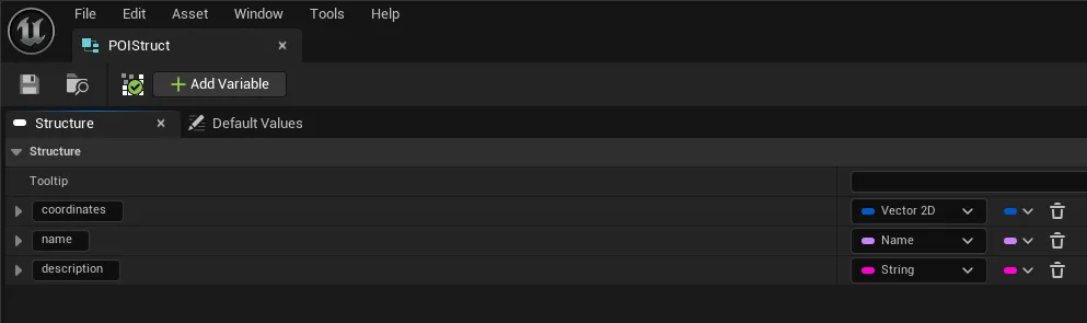
In the content browser, create a POIStruct that will hold all the information we need for the POIs. Create a struct with fields:
- coordinates - type:
Vector 2D- to hold the x and y coordinates of the actor. - name - type:
name- to hold the name of the POI. - description - type:
string- to hold the description of the POI that will be shown in the tooltip.
Let’s do the same for the area markers. The fields will be the same, except we don’t need description as the elements will be just text.
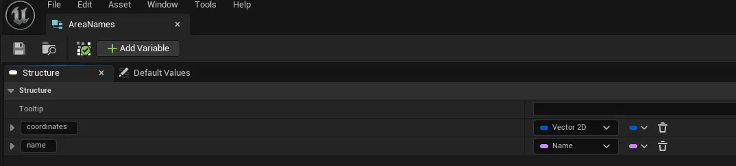
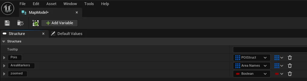
The last struct we need is for the model we are going to use in the UI. Create a structure named MapModel that will hold:
- An array of
POIStructelements. - An array of
AreaMarkerselements. - zoomed -
booleanflag we will use to toggle styles in the UI relative to the zoom level of the map.
Each element in these arrays will be bound to the actors in our world.
Setting Up the Points of Interest
After the actors have been placed in the world, we can now work with their data.
Head to the Event graph in the GameState BP and create a new method called Init Variables. There we will initialize and connect the actors with the structs we have
just created, as well as initialize some other variables.
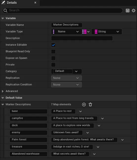
To fill the structs with information for the POIs, create a variable called Marker Descriptions with Map type where we will define the description of the POIs.
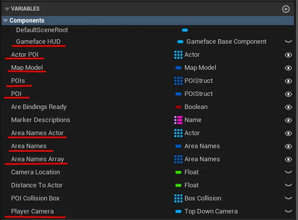
Lastly, create all the other variables we are going to need for our logic.
Expand to view variable description
- Gameface HUD - Will be used to hold reference to the
GameFace HUDobject. - Actor POI - Here we will store the actors for the points of interest.
- Map Model - This is our model, which will interact with our UI.
- POIs - An array of
POIStructelements, which will hold the info about the POIs data. - POI - Instance of the
POIStructtype, which we will use to map POI data and add it to the POIs array. - Area Names Actor - Same purpose as the Actor POI variable but for the area markers.
- Area Names - Same purpose as the POI variable but for the area markers.
- Area Names Array - Same purpose as the POIs variable but for the area markers.
- Player Camera - Will be used to hold reference to the camera object.
With that out of the way, let’s finally set up the blueprint logic for this method.
- First, set the reference for the
GameFace HUDand the Camera objects. - Then, get all actors with tag
POIand set them in theActor POIarray. - Loop through the array and for each entry, get the tag with index 0 - which is the POI’s type (enemy, treasure, etc.) and find the corresponding
element from the
Marker Descriptionsarray to find the appropriate description for the POI. - Next, set the members (
nameanddescription) inPOIStruct. - Lastly, add the newly created POI to the POIs array.
- Repeat the process for the area markers, with the exception that they don’t have a description field, so this part is skipped.
   Begin Object Class=/Script/BlueprintGraph.K2Node_FunctionEntry Name="K2Node_FunctionEntry_1" ExportPath="/Script/BlueprintGraph.K2Node_FunctionEntry'/Game/MapAssets/3DMap/3DMapGameState.3DMapGameState:Init Variables.K2Node_FunctionEntry_1'"
   MetaData=(Category=NSLOCTEXT("KismetSchema", "Default", "Default"))
   ExtraFlags=201457664
   FunctionReference=(MemberName="Init Variables")
   bIsEditable=True
   NodePosX=-656
   NodePosY=16
   NodeGuid=3052B0A54524D7274AAAC784046FB5C4
   CustomProperties Pin (PinId=34236F2A4ACFFBC05E786DBFB3D6D622,PinName="then",Direction="EGPD_Output",PinType.PinCategory="exec",PinType.PinSubCategory="",PinType.PinSubCategoryObject=None,PinType.PinSubCategoryMemberReference=(),PinType.PinValueType=(),PinType.ContainerType=None,PinType.bIsReference=False,PinType.bIsConst=False,PinType.bIsWeakPointer=False,PinType.bIsUObjectWrapper=False,PinType.bSerializeAsSinglePrecisionFloat=False,LinkedTo=(K2Node_DynamicCast_6 698FAA1C4365DE4ADC712284F46D14BC,),PersistentGuid=00000000000000000000000000000000,bHidden=False,bNotConnectable=False,bDefaultValueIsReadOnly=False,bDefaultValueIsIgnored=False,bAdvancedView=False,bOrphanedPin=False,)
End Object
Begin Object Class=/Script/BlueprintGraph.K2Node_CallFunction Name="K2Node_CallFunction_4" ExportPath="/Script/BlueprintGraph.K2Node_CallFunction'/Game/MapAssets/3DMap/3DMapGameState.3DMapGameState:Init Variables.K2Node_CallFunction_4'"
   FunctionReference=(MemberParent="/Script/CoreUObject.Class'/Script/Engine.GameplayStatics'",MemberName="GetAllActorsOfClassWithTag")
   NodePosX=1392
   NodePosY=16
   NodeGuid=8DDBFB6B40E2081F6CD884AB54E7E0BD
   CustomProperties Pin (PinId=9C19AB28471C6268972B4CA72FC2A7BD,PinName="execute",PinType.PinCategory="exec",PinType.PinSubCategory="",PinType.PinSubCategoryObject=None,PinType.PinSubCategoryMemberReference=(),PinType.PinValueType=(),PinType.ContainerType=None,PinType.bIsReference=False,PinType.bIsConst=False,PinType.bIsWeakPointer=False,PinType.bIsUObjectWrapper=False,PinType.bSerializeAsSinglePrecisionFloat=False,LinkedTo=(K2Node_ExecutionSequence_0 70B27EF3472C8B525732C286F969E6A4,),PersistentGuid=00000000000000000000000000000000,bHidden=False,bNotConnectable=False,bDefaultValueIsReadOnly=False,bDefaultValueIsIgnored=False,bAdvancedView=False,bOrphanedPin=False,)
   CustomProperties Pin (PinId=5EE9896F4AA06535747BD6872E239A29,PinName="then",Direction="EGPD_Output",PinType.PinCategory="exec",PinType.PinSubCategory="",PinType.PinSubCategoryObject=None,PinType.PinSubCategoryMemberReference=(),PinType.PinValueType=(),PinType.ContainerType=None,PinType.bIsReference=False,PinType.bIsConst=False,PinType.bIsWeakPointer=False,PinType.bIsUObjectWrapper=False,PinType.bSerializeAsSinglePrecisionFloat=False,LinkedTo=(K2Node_VariableSet_0 DF61652249ACD0EE13EC8EB63746F231,),PersistentGuid=00000000000000000000000000000000,bHidden=False,bNotConnectable=False,bDefaultValueIsReadOnly=False,bDefaultValueIsIgnored=False,bAdvancedView=False,bOrphanedPin=False,)
   CustomProperties Pin (PinId=CA5849E1459A2CACF695C78E87D7D26B,PinName="self",PinFriendlyName=NSLOCTEXT("K2Node", "Target", "Target"),PinType.PinCategory="object",PinType.PinSubCategory="",PinType.PinSubCategoryObject="/Script/CoreUObject.Class'/Script/Engine.GameplayStatics'",PinType.PinSubCategoryMemberReference=(),PinType.PinValueType=(),PinType.ContainerType=None,PinType.bIsReference=False,PinType.bIsConst=False,PinType.bIsWeakPointer=False,PinType.bIsUObjectWrapper=False,PinType.bSerializeAsSinglePrecisionFloat=False,DefaultObject="/Script/Engine.Default__GameplayStatics",PersistentGuid=00000000000000000000000000000000,bHidden=True,bNotConnectable=False,bDefaultValueIsReadOnly=False,bDefaultValueIsIgnored=False,bAdvancedView=False,bOrphanedPin=False,)
   CustomProperties Pin (PinId=B8C2C3BD4FC5F3328C2DE8BC2BB744AB,PinName="WorldContextObject",PinType.PinCategory="object",PinType.PinSubCategory="",PinType.PinSubCategoryObject="/Script/CoreUObject.Class'/Script/CoreUObject.Object'",PinType.PinSubCategoryMemberReference=(),PinType.PinValueType=(),PinType.ContainerType=None,PinType.bIsReference=False,PinType.bIsConst=True,PinType.bIsWeakPointer=False,PinType.bIsUObjectWrapper=False,PinType.bSerializeAsSinglePrecisionFloat=False,PersistentGuid=00000000000000000000000000000000,bHidden=True,bNotConnectable=False,bDefaultValueIsReadOnly=False,bDefaultValueIsIgnored=False,bAdvancedView=False,bOrphanedPin=False,)
   CustomProperties Pin (PinId=E1AFBC1E4EDBC039CFD21A898330D905,PinName="ActorClass",PinType.PinCategory="class",PinType.PinSubCategory="",PinType.PinSubCategoryObject="/Script/CoreUObject.Class'/Script/Engine.Actor'",PinType.PinSubCategoryMemberReference=(),PinType.PinValueType=(),PinType.ContainerType=None,PinType.bIsReference=False,PinType.bIsConst=False,PinType.bIsWeakPointer=False,PinType.bIsUObjectWrapper=True,PinType.bSerializeAsSinglePrecisionFloat=False,DefaultObject="/Script/Engine.Actor",PersistentGuid=00000000000000000000000000000000,bHidden=False,bNotConnectable=False,bDefaultValueIsReadOnly=False,bDefaultValueIsIgnored=False,bAdvancedView=False,bOrphanedPin=False,)
   CustomProperties Pin (PinId=1CB76E9D45586B50BD71248765D236D4,PinName="Tag",PinType.PinCategory="name",PinType.PinSubCategory="",PinType.PinSubCategoryObject=None,PinType.PinSubCategoryMemberReference=(),PinType.PinValueType=(),PinType.ContainerType=None,PinType.bIsReference=False,PinType.bIsConst=False,PinType.bIsWeakPointer=False,PinType.bIsUObjectWrapper=False,PinType.bSerializeAsSinglePrecisionFloat=False,DefaultValue="POI",AutogeneratedDefaultValue="None",PersistentGuid=00000000000000000000000000000000,bHidden=False,bNotConnectable=False,bDefaultValueIsReadOnly=False,bDefaultValueIsIgnored=False,bAdvancedView=False,bOrphanedPin=False,)
   CustomProperties Pin (PinId=536602154E5B68E6E1298CAF6EC9327D,PinName="OutActors",Direction="EGPD_Output",PinType.PinCategory="object",PinType.PinSubCategory="",PinType.PinSubCategoryObject="/Script/CoreUObject.Class'/Script/Engine.Actor'",PinType.PinSubCategoryMemberReference=(),PinType.PinValueType=(),PinType.ContainerType=Array,PinType.bIsReference=False,PinType.bIsConst=False,PinType.bIsWeakPointer=False,PinType.bIsUObjectWrapper=False,PinType.bSerializeAsSinglePrecisionFloat=False,LinkedTo=(K2Node_VariableSet_0 5D17B5374D492C5AD592C195C35678A9,),PersistentGuid=00000000000000000000000000000000,bHidden=False,bNotConnectable=False,bDefaultValueIsReadOnly=False,bDefaultValueIsIgnored=False,bAdvancedView=False,bOrphanedPin=False,)
End Object
Begin Object Class=/Script/BlueprintGraph.K2Node_CallFunction Name="K2Node_CallFunction_0" ExportPath="/Script/BlueprintGraph.K2Node_CallFunction'/Game/MapAssets/3DMap/3DMapGameState.3DMapGameState:Init Variables.K2Node_CallFunction_0'"
   bIsPureFunc=True
   FunctionReference=(MemberParent="/Script/CoreUObject.Class'/Script/Engine.GameplayStatics'",MemberName="GetPlayerController")
   NodePosX=-896
   NodePosY=176
   NodeGuid=43337DEB46049AAFE1DC98920CE82EF2
   CustomProperties Pin (PinId=065F9A8642E2B58EA4A897860A32E153,PinName="self",PinFriendlyName=NSLOCTEXT("K2Node", "Target", "Target"),PinType.PinCategory="object",PinType.PinSubCategory="",PinType.PinSubCategoryObject="/Script/CoreUObject.Class'/Script/Engine.GameplayStatics'",PinType.PinSubCategoryMemberReference=(),PinType.PinValueType=(),PinType.ContainerType=None,PinType.bIsReference=False,PinType.bIsConst=False,PinType.bIsWeakPointer=False,PinType.bIsUObjectWrapper=False,PinType.bSerializeAsSinglePrecisionFloat=False,DefaultObject="/Script/Engine.Default__GameplayStatics",PersistentGuid=00000000000000000000000000000000,bHidden=True,bNotConnectable=False,bDefaultValueIsReadOnly=False,bDefaultValueIsIgnored=False,bAdvancedView=False,bOrphanedPin=False,)
   CustomProperties Pin (PinId=DF39DF2C4C27EF2334F4BDA2F5052950,PinName="WorldContextObject",PinType.PinCategory="object",PinType.PinSubCategory="",PinType.PinSubCategoryObject="/Script/CoreUObject.Class'/Script/CoreUObject.Object'",PinType.PinSubCategoryMemberReference=(),PinType.PinValueType=(),PinType.ContainerType=None,PinType.bIsReference=False,PinType.bIsConst=True,PinType.bIsWeakPointer=False,PinType.bIsUObjectWrapper=False,PinType.bSerializeAsSinglePrecisionFloat=False,PersistentGuid=00000000000000000000000000000000,bHidden=True,bNotConnectable=False,bDefaultValueIsReadOnly=False,bDefaultValueIsIgnored=False,bAdvancedView=False,bOrphanedPin=False,)
   CustomProperties Pin (PinId=A410852C4810E34A463F3CBA3D56860B,PinName="PlayerIndex",PinType.PinCategory="int",PinType.PinSubCategory="",PinType.PinSubCategoryObject=None,PinType.PinSubCategoryMemberReference=(),PinType.PinValueType=(),PinType.ContainerType=None,PinType.bIsReference=False,PinType.bIsConst=False,PinType.bIsWeakPointer=False,PinType.bIsUObjectWrapper=False,PinType.bSerializeAsSinglePrecisionFloat=False,DefaultValue="0",AutogeneratedDefaultValue="0",PersistentGuid=00000000000000000000000000000000,bHidden=False,bNotConnectable=False,bDefaultValueIsReadOnly=False,bDefaultValueIsIgnored=False,bAdvancedView=False,bOrphanedPin=False,)
   CustomProperties Pin (PinId=C4DDBB884726A5D4827DA8A0401B0E88,PinName="ReturnValue",Direction="EGPD_Output",PinType.PinCategory="object",PinType.PinSubCategory="",PinType.PinSubCategoryObject="/Script/CoreUObject.Class'/Script/Engine.PlayerController'",PinType.PinSubCategoryMemberReference=(),PinType.PinValueType=(),PinType.ContainerType=None,PinType.bIsReference=False,PinType.bIsConst=False,PinType.bIsWeakPointer=False,PinType.bIsUObjectWrapper=False,PinType.bSerializeAsSinglePrecisionFloat=False,LinkedTo=(K2Node_CallFunction_1 C56CEC4D4982E51C7F214EBBDA53170F,),PersistentGuid=00000000000000000000000000000000,bHidden=False,bNotConnectable=False,bDefaultValueIsReadOnly=False,bDefaultValueIsIgnored=False,bAdvancedView=False,bOrphanedPin=False,)
End Object
Begin Object Class=/Script/BlueprintGraph.K2Node_CallFunction Name="K2Node_CallFunction_1" ExportPath="/Script/BlueprintGraph.K2Node_CallFunction'/Game/MapAssets/3DMap/3DMapGameState.3DMapGameState:Init Variables.K2Node_CallFunction_1'"
   bIsPureFunc=True
   bIsConstFunc=True
   FunctionReference=(MemberParent="/Script/CoreUObject.Class'/Script/Engine.PlayerController'",MemberName="GetHUD")
   NodePosX=-608
   NodePosY=160
   ErrorType=3
   NodeGuid=59A65CD643BB26A621D1B39E9122E619
   CustomProperties Pin (PinId=C56CEC4D4982E51C7F214EBBDA53170F,PinName="self",PinFriendlyName=NSLOCTEXT("K2Node", "Target", "Target"),PinType.PinCategory="object",PinType.PinSubCategory="",PinType.PinSubCategoryObject="/Script/CoreUObject.Class'/Script/Engine.PlayerController'",PinType.PinSubCategoryMemberReference=(),PinType.PinValueType=(),PinType.ContainerType=None,PinType.bIsReference=False,PinType.bIsConst=False,PinType.bIsWeakPointer=False,PinType.bIsUObjectWrapper=False,PinType.bSerializeAsSinglePrecisionFloat=False,LinkedTo=(K2Node_CallFunction_0 C4DDBB884726A5D4827DA8A0401B0E88,),PersistentGuid=00000000000000000000000000000000,bHidden=False,bNotConnectable=False,bDefaultValueIsReadOnly=False,bDefaultValueIsIgnored=False,bAdvancedView=False,bOrphanedPin=False,)
   CustomProperties Pin (PinId=6C2074AF4C46CBB9080869A49CD42C1B,PinName="ReturnValue",Direction="EGPD_Output",PinType.PinCategory="object",PinType.PinSubCategory="",PinType.PinSubCategoryObject="/Script/CoreUObject.Class'/Script/Engine.HUD'",PinType.PinSubCategoryMemberReference=(),PinType.PinValueType=(),PinType.ContainerType=None,PinType.bIsReference=False,PinType.bIsConst=False,PinType.bIsWeakPointer=False,PinType.bIsUObjectWrapper=False,PinType.bSerializeAsSinglePrecisionFloat=False,LinkedTo=(K2Node_DynamicCast_6 D93DB71144987047D1AA8DBBDD832829,),PersistentGuid=00000000000000000000000000000000,bHidden=False,bNotConnectable=False,bDefaultValueIsReadOnly=False,bDefaultValueIsIgnored=False,bAdvancedView=False,bOrphanedPin=False,)
End Object
Begin Object Class=/Script/BlueprintGraph.K2Node_DynamicCast Name="K2Node_DynamicCast_6" ExportPath="/Script/BlueprintGraph.K2Node_DynamicCast'/Game/MapAssets/3DMap/3DMapGameState.3DMapGameState:Init Variables.K2Node_DynamicCast_6'"
   TargetType="/Script/CoreUObject.Class'/Script/CohtmlPlugin.CohtmlGameHUD'"
   NodePosX=-352
   NodePosY=16
   NodeGuid=E805A1D74A702B3A5A38818E7CA78511
   CustomProperties Pin (PinId=698FAA1C4365DE4ADC712284F46D14BC,PinName="execute",PinType.PinCategory="exec",PinType.PinSubCategory="",PinType.PinSubCategoryObject=None,PinType.PinSubCategoryMemberReference=(),PinType.PinValueType=(),PinType.ContainerType=None,PinType.bIsReference=False,PinType.bIsConst=False,PinType.bIsWeakPointer=False,PinType.bIsUObjectWrapper=False,PinType.bSerializeAsSinglePrecisionFloat=False,LinkedTo=(K2Node_FunctionEntry_1 34236F2A4ACFFBC05E786DBFB3D6D622,),PersistentGuid=00000000000000000000000000000000,bHidden=False,bNotConnectable=False,bDefaultValueIsReadOnly=False,bDefaultValueIsIgnored=False,bAdvancedView=False,bOrphanedPin=False,)
   CustomProperties Pin (PinId=2FF3E83649FDFF04C9A47A844AFFA94C,PinName="then",Direction="EGPD_Output",PinType.PinCategory="exec",PinType.PinSubCategory="",PinType.PinSubCategoryObject=None,PinType.PinSubCategoryMemberReference=(),PinType.PinValueType=(),PinType.ContainerType=None,PinType.bIsReference=False,PinType.bIsConst=False,PinType.bIsWeakPointer=False,PinType.bIsUObjectWrapper=False,PinType.bSerializeAsSinglePrecisionFloat=False,LinkedTo=(K2Node_VariableSet_2 0750950847DE29B138C9A39378B617A4,),PersistentGuid=00000000000000000000000000000000,bHidden=False,bNotConnectable=False,bDefaultValueIsReadOnly=False,bDefaultValueIsIgnored=False,bAdvancedView=False,bOrphanedPin=False,)
   CustomProperties Pin (PinId=8EE978994C66914D8FC89AA758B2598E,PinName="CastFailed",Direction="EGPD_Output",PinType.PinCategory="exec",PinType.PinSubCategory="",PinType.PinSubCategoryObject=None,PinType.PinSubCategoryMemberReference=(),PinType.PinValueType=(),PinType.ContainerType=None,PinType.bIsReference=False,PinType.bIsConst=False,PinType.bIsWeakPointer=False,PinType.bIsUObjectWrapper=False,PinType.bSerializeAsSinglePrecisionFloat=False,PersistentGuid=00000000000000000000000000000000,bHidden=False,bNotConnectable=False,bDefaultValueIsReadOnly=False,bDefaultValueIsIgnored=False,bAdvancedView=False,bOrphanedPin=False,)
   CustomProperties Pin (PinId=D93DB71144987047D1AA8DBBDD832829,PinName="Object",PinType.PinCategory="object",PinType.PinSubCategory="",PinType.PinSubCategoryObject="/Script/CoreUObject.Class'/Script/CoreUObject.Object'",PinType.PinSubCategoryMemberReference=(),PinType.PinValueType=(),PinType.ContainerType=None,PinType.bIsReference=False,PinType.bIsConst=False,PinType.bIsWeakPointer=False,PinType.bIsUObjectWrapper=False,PinType.bSerializeAsSinglePrecisionFloat=False,LinkedTo=(K2Node_CallFunction_1 6C2074AF4C46CBB9080869A49CD42C1B,),PersistentGuid=00000000000000000000000000000000,bHidden=False,bNotConnectable=False,bDefaultValueIsReadOnly=False,bDefaultValueIsIgnored=False,bAdvancedView=False,bOrphanedPin=False,)
   CustomProperties Pin (PinId=6E4BFE214D6DD76F93703F8582D334B2,PinName="AsGameface GameHUD",Direction="EGPD_Output",PinType.PinCategory="object",PinType.PinSubCategory="",PinType.PinSubCategoryObject="/Script/CoreUObject.Class'/Script/CohtmlPlugin.CohtmlGameHUD'",PinType.PinSubCategoryMemberReference=(),PinType.PinValueType=(),PinType.ContainerType=None,PinType.bIsReference=False,PinType.bIsConst=False,PinType.bIsWeakPointer=False,PinType.bIsUObjectWrapper=False,PinType.bSerializeAsSinglePrecisionFloat=False,LinkedTo=(K2Node_VariableGet_6 2B98711347860385894872B06AC06EC7,),PersistentGuid=00000000000000000000000000000000,bHidden=False,bNotConnectable=False,bDefaultValueIsReadOnly=False,bDefaultValueIsIgnored=False,bAdvancedView=False,bOrphanedPin=False,)
   CustomProperties Pin (PinId=0241E42D453860F45E4A3DB51B3D7BCB,PinName="bSuccess",Direction="EGPD_Output",PinType.PinCategory="bool",PinType.PinSubCategory="",PinType.PinSubCategoryObject=None,PinType.PinSubCategoryMemberReference=(),PinType.PinValueType=(),PinType.ContainerType=None,PinType.bIsReference=False,PinType.bIsConst=False,PinType.bIsWeakPointer=False,PinType.bIsUObjectWrapper=False,PinType.bSerializeAsSinglePrecisionFloat=False,PersistentGuid=00000000000000000000000000000000,bHidden=True,bNotConnectable=False,bDefaultValueIsReadOnly=False,bDefaultValueIsIgnored=False,bAdvancedView=False,bOrphanedPin=False,)
End Object
Begin Object Class=/Script/BlueprintGraph.K2Node_VariableSet Name="K2Node_VariableSet_2" ExportPath="/Script/BlueprintGraph.K2Node_VariableSet'/Game/MapAssets/3DMap/3DMapGameState.3DMapGameState:Init Variables.K2Node_VariableSet_2'"
   VariableReference=(MemberName="GameFace HUD",MemberGuid=86FE453C4F22CCE4D4D139BA1647D58F,bSelfContext=True)
   NodePosX=176
   NodePosY=32
   ErrorType=1
   NodeGuid=CE4A127D4BCED86DA988F8B99F00FD03
   CustomProperties Pin (PinId=0750950847DE29B138C9A39378B617A4,PinName="execute",PinType.PinCategory="exec",PinType.PinSubCategory="",PinType.PinSubCategoryObject=None,PinType.PinSubCategoryMemberReference=(),PinType.PinValueType=(),PinType.ContainerType=None,PinType.bIsReference=False,PinType.bIsConst=False,PinType.bIsWeakPointer=False,PinType.bIsUObjectWrapper=False,PinType.bSerializeAsSinglePrecisionFloat=False,LinkedTo=(K2Node_DynamicCast_6 2FF3E83649FDFF04C9A47A844AFFA94C,),PersistentGuid=00000000000000000000000000000000,bHidden=False,bNotConnectable=False,bDefaultValueIsReadOnly=False,bDefaultValueIsIgnored=False,bAdvancedView=False,bOrphanedPin=False,)
   CustomProperties Pin (PinId=D9A45D384D333EF1A4FCDF989478646B,PinName="then",Direction="EGPD_Output",PinType.PinCategory="exec",PinType.PinSubCategory="",PinType.PinSubCategoryObject=None,PinType.PinSubCategoryMemberReference=(),PinType.PinValueType=(),PinType.ContainerType=None,PinType.bIsReference=False,PinType.bIsConst=False,PinType.bIsWeakPointer=False,PinType.bIsUObjectWrapper=False,PinType.bSerializeAsSinglePrecisionFloat=False,LinkedTo=(K2Node_DynamicCast_0 D727F2594C9A9496826920983184ED3A,),PersistentGuid=00000000000000000000000000000000,bHidden=False,bNotConnectable=False,bDefaultValueIsReadOnly=False,bDefaultValueIsIgnored=False,bAdvancedView=False,bOrphanedPin=False,)
   CustomProperties Pin (PinId=91B7C11B439EEFEFFA1416B9DF3A1264,PinName="GameFace HUD",PinType.PinCategory="object",PinType.PinSubCategory="",PinType.PinSubCategoryObject="/Script/CoreUObject.Class'/Script/CohtmlPlugin.CohtmlBaseComponent'",PinType.PinSubCategoryMemberReference=(),PinType.PinValueType=(),PinType.ContainerType=None,PinType.bIsReference=False,PinType.bIsConst=False,PinType.bIsWeakPointer=False,PinType.bIsUObjectWrapper=False,PinType.bSerializeAsSinglePrecisionFloat=False,LinkedTo=(K2Node_VariableGet_6 6386698349CA3B8249AECFBA74F7C889,),PersistentGuid=00000000000000000000000000000000,bHidden=False,bNotConnectable=False,bDefaultValueIsReadOnly=False,bDefaultValueIsIgnored=False,bAdvancedView=False,bOrphanedPin=False,)
   CustomProperties Pin (PinId=BBF8904A4EF0B05EC4F81CACA4A231D6,PinName="Output_Get",PinToolTip="Retrieves the value of the variable, can use instead of a separate Get node",Direction="EGPD_Output",PinType.PinCategory="object",PinType.PinSubCategory="",PinType.PinSubCategoryObject="/Script/CoreUObject.Class'/Script/CohtmlPlugin.CohtmlBaseComponent'",PinType.PinSubCategoryMemberReference=(),PinType.PinValueType=(),PinType.ContainerType=None,PinType.bIsReference=False,PinType.bIsConst=False,PinType.bIsWeakPointer=False,PinType.bIsUObjectWrapper=False,PinType.bSerializeAsSinglePrecisionFloat=False,PersistentGuid=00000000000000000000000000000000,bHidden=False,bNotConnectable=False,bDefaultValueIsReadOnly=False,bDefaultValueIsIgnored=False,bAdvancedView=False,bOrphanedPin=False,)
   CustomProperties Pin (PinId=D9686C934736687592F27E87B1A4B5B1,PinName="self",PinFriendlyName=NSLOCTEXT("K2Node", "Target", "Target"),PinType.PinCategory="object",PinType.PinSubCategory="",PinType.PinSubCategoryObject="/Script/Engine.BlueprintGeneratedClass'/Game/MapAssets/3DMap/3DMapGameState.3DMapGameState_C'",PinType.PinSubCategoryMemberReference=(),PinType.PinValueType=(),PinType.ContainerType=None,PinType.bIsReference=False,PinType.bIsConst=False,PinType.bIsWeakPointer=False,PinType.bIsUObjectWrapper=False,PinType.bSerializeAsSinglePrecisionFloat=False,PersistentGuid=00000000000000000000000000000000,bHidden=True,bNotConnectable=False,bDefaultValueIsReadOnly=False,bDefaultValueIsIgnored=False,bAdvancedView=False,bOrphanedPin=False,)
End Object
Begin Object Class=/Script/BlueprintGraph.K2Node_VariableSet Name="K2Node_VariableSet_0" ExportPath="/Script/BlueprintGraph.K2Node_VariableSet'/Game/MapAssets/3DMap/3DMapGameState.3DMapGameState:Init Variables.K2Node_VariableSet_0'"
   VariableReference=(MemberName="Actor POI",MemberGuid=C9EE85BF4A950CCF7B3C9C965AD8A047,bSelfContext=True)
   NodePosX=1712
   NodePosY=32
   ErrorType=1
   NodeGuid=3CA120164E2FA5423C12B8BF372E5412
   CustomProperties Pin (PinId=DF61652249ACD0EE13EC8EB63746F231,PinName="execute",PinType.PinCategory="exec",PinType.PinSubCategory="",PinType.PinSubCategoryObject=None,PinType.PinSubCategoryMemberReference=(),PinType.PinValueType=(),PinType.ContainerType=None,PinType.bIsReference=False,PinType.bIsConst=False,PinType.bIsWeakPointer=False,PinType.bIsUObjectWrapper=False,PinType.bSerializeAsSinglePrecisionFloat=False,LinkedTo=(K2Node_CallFunction_4 5EE9896F4AA06535747BD6872E239A29,),PersistentGuid=00000000000000000000000000000000,bHidden=False,bNotConnectable=False,bDefaultValueIsReadOnly=False,bDefaultValueIsIgnored=False,bAdvancedView=False,bOrphanedPin=False,)
   CustomProperties Pin (PinId=3666DCFD4043B759BC422ABC2793ED13,PinName="then",Direction="EGPD_Output",PinType.PinCategory="exec",PinType.PinSubCategory="",PinType.PinSubCategoryObject=None,PinType.PinSubCategoryMemberReference=(),PinType.PinValueType=(),PinType.ContainerType=None,PinType.bIsReference=False,PinType.bIsConst=False,PinType.bIsWeakPointer=False,PinType.bIsUObjectWrapper=False,PinType.bSerializeAsSinglePrecisionFloat=False,LinkedTo=(K2Node_MacroInstance_1 A95307ED4BDF236D15586F9863552C84,),PersistentGuid=00000000000000000000000000000000,bHidden=False,bNotConnectable=False,bDefaultValueIsReadOnly=False,bDefaultValueIsIgnored=False,bAdvancedView=False,bOrphanedPin=False,)
   CustomProperties Pin (PinId=5D17B5374D492C5AD592C195C35678A9,PinName="Actor POI",PinType.PinCategory="object",PinType.PinSubCategory="",PinType.PinSubCategoryObject="/Script/CoreUObject.Class'/Script/Engine.Actor'",PinType.PinSubCategoryMemberReference=(),PinType.PinValueType=(),PinType.ContainerType=Array,PinType.bIsReference=False,PinType.bIsConst=False,PinType.bIsWeakPointer=False,PinType.bIsUObjectWrapper=False,PinType.bSerializeAsSinglePrecisionFloat=False,LinkedTo=(K2Node_CallFunction_4 536602154E5B68E6E1298CAF6EC9327D,),PersistentGuid=00000000000000000000000000000000,bHidden=False,bNotConnectable=False,bDefaultValueIsReadOnly=False,bDefaultValueIsIgnored=False,bAdvancedView=False,bOrphanedPin=False,)
   CustomProperties Pin (PinId=CDF305A84C525EB37386ED8DA5717AE0,PinName="Output_Get",PinToolTip="Retrieves the value of the variable, can use instead of a separate Get node",Direction="EGPD_Output",PinType.PinCategory="object",PinType.PinSubCategory="",PinType.PinSubCategoryObject="/Script/CoreUObject.Class'/Script/Engine.Actor'",PinType.PinSubCategoryMemberReference=(),PinType.PinValueType=(),PinType.ContainerType=Array,PinType.bIsReference=False,PinType.bIsConst=False,PinType.bIsWeakPointer=False,PinType.bIsUObjectWrapper=False,PinType.bSerializeAsSinglePrecisionFloat=False,LinkedTo=(K2Node_MacroInstance_1 4FFFA544419D7D8A11AA2E8CD22E6E16,),PersistentGuid=00000000000000000000000000000000,bHidden=False,bNotConnectable=False,bDefaultValueIsReadOnly=False,bDefaultValueIsIgnored=False,bAdvancedView=False,bOrphanedPin=False,)
   CustomProperties Pin (PinId=E2590340433FBF60BCDE60830B38D082,PinName="self",PinFriendlyName=NSLOCTEXT("K2Node", "Target", "Target"),PinType.PinCategory="object",PinType.PinSubCategory="",PinType.PinSubCategoryObject="/Script/Engine.BlueprintGeneratedClass'/Game/MapAssets/3DMap/3DMapGameState.3DMapGameState_C'",PinType.PinSubCategoryMemberReference=(),PinType.PinValueType=(),PinType.ContainerType=None,PinType.bIsReference=False,PinType.bIsConst=False,PinType.bIsWeakPointer=False,PinType.bIsUObjectWrapper=False,PinType.bSerializeAsSinglePrecisionFloat=False,PersistentGuid=00000000000000000000000000000000,bHidden=True,bNotConnectable=False,bDefaultValueIsReadOnly=False,bDefaultValueIsIgnored=False,bAdvancedView=False,bOrphanedPin=False,)
End Object
Begin Object Class=/Script/BlueprintGraph.K2Node_MacroInstance Name="K2Node_MacroInstance_1" ExportPath="/Script/BlueprintGraph.K2Node_MacroInstance'/Game/MapAssets/3DMap/3DMapGameState.3DMapGameState:Init Variables.K2Node_MacroInstance_1'"
   MacroGraphReference=(MacroGraph="/Script/Engine.EdGraph'/Engine/EditorBlueprintResources/StandardMacros.StandardMacros:ForEachLoop'",GraphBlueprint="/Script/Engine.Blueprint'/Engine/EditorBlueprintResources/StandardMacros.StandardMacros'",GraphGuid=99DBFD5540A796041F72A5A9DA655026)
   ResolvedWildcardType=(PinCategory="object",PinSubCategoryObject="/Script/CoreUObject.Class'/Script/Engine.Actor'",ContainerType=Array)
   NodePosX=1904
   NodePosY=16
   ErrorType=1
   NodeGuid=41E5555847DA1E171159298DA2E9C3DF
   CustomProperties Pin (PinId=A95307ED4BDF236D15586F9863552C84,PinName="Exec",PinType.PinCategory="exec",PinType.PinSubCategory="",PinType.PinSubCategoryObject=None,PinType.PinSubCategoryMemberReference=(),PinType.PinValueType=(),PinType.ContainerType=None,PinType.bIsReference=False,PinType.bIsConst=False,PinType.bIsWeakPointer=False,PinType.bIsUObjectWrapper=False,PinType.bSerializeAsSinglePrecisionFloat=False,LinkedTo=(K2Node_VariableSet_0 3666DCFD4043B759BC422ABC2793ED13,),PersistentGuid=00000000000000000000000000000000,bHidden=False,bNotConnectable=False,bDefaultValueIsReadOnly=False,bDefaultValueIsIgnored=False,bAdvancedView=False,bOrphanedPin=False,)
   CustomProperties Pin (PinId=4FFFA544419D7D8A11AA2E8CD22E6E16,PinName="Array",PinType.PinCategory="object",PinType.PinSubCategory="",PinType.PinSubCategoryObject="/Script/CoreUObject.Class'/Script/Engine.Actor'",PinType.PinSubCategoryMemberReference=(),PinType.PinValueType=(),PinType.ContainerType=Array,PinType.bIsReference=False,PinType.bIsConst=False,PinType.bIsWeakPointer=False,PinType.bIsUObjectWrapper=False,PinType.bSerializeAsSinglePrecisionFloat=False,LinkedTo=(K2Node_VariableSet_0 CDF305A84C525EB37386ED8DA5717AE0,),PersistentGuid=00000000000000000000000000000000,bHidden=False,bNotConnectable=False,bDefaultValueIsReadOnly=False,bDefaultValueIsIgnored=False,bAdvancedView=False,bOrphanedPin=False,)
   CustomProperties Pin (PinId=A497B005455FE81B5BA395A66C427D43,PinName="LoopBody",Direction="EGPD_Output",PinType.PinCategory="exec",PinType.PinSubCategory="",PinType.PinSubCategoryObject=None,PinType.PinSubCategoryMemberReference=(),PinType.PinValueType=(),PinType.ContainerType=None,PinType.bIsReference=False,PinType.bIsConst=False,PinType.bIsWeakPointer=False,PinType.bIsUObjectWrapper=False,PinType.bSerializeAsSinglePrecisionFloat=False,LinkedTo=(K2Node_SetFieldsInStruct_1 2181FAD94C13BD79A369B7B30BCAF235,),PersistentGuid=00000000000000000000000000000000,bHidden=False,bNotConnectable=False,bDefaultValueIsReadOnly=False,bDefaultValueIsIgnored=False,bAdvancedView=False,bOrphanedPin=False,)
   CustomProperties Pin (PinId=13251EAA45B5F7993EAD2EB399441509,PinName="Array Element",Direction="EGPD_Output",PinType.PinCategory="object",PinType.PinSubCategory="",PinType.PinSubCategoryObject="/Script/CoreUObject.Class'/Script/Engine.Actor'",PinType.PinSubCategoryMemberReference=(),PinType.PinValueType=(),PinType.ContainerType=None,PinType.bIsReference=False,PinType.bIsConst=False,PinType.bIsWeakPointer=False,PinType.bIsUObjectWrapper=False,PinType.bSerializeAsSinglePrecisionFloat=False,LinkedTo=(K2Node_VariableGet_2 8F4DAFA4415EA3E56BC40C9F66FFAAFD,),PersistentGuid=00000000000000000000000000000000,bHidden=False,bNotConnectable=False,bDefaultValueIsReadOnly=False,bDefaultValueIsIgnored=False,bAdvancedView=False,bOrphanedPin=False,)
   CustomProperties Pin (PinId=803BC1064BC7FAE1CD9307A57AE0C471,PinName="Array Index",Direction="EGPD_Output",PinType.PinCategory="int",PinType.PinSubCategory="",PinType.PinSubCategoryObject=None,PinType.PinSubCategoryMemberReference=(),PinType.PinValueType=(),PinType.ContainerType=None,PinType.bIsReference=False,PinType.bIsConst=False,PinType.bIsWeakPointer=False,PinType.bIsUObjectWrapper=False,PinType.bSerializeAsSinglePrecisionFloat=False,PersistentGuid=00000000000000000000000000000000,bHidden=False,bNotConnectable=False,bDefaultValueIsReadOnly=False,bDefaultValueIsIgnored=False,bAdvancedView=False,bOrphanedPin=False,)
   CustomProperties Pin (PinId=23D4F4BD4C807C469870F897819D11AC,PinName="Completed",Direction="EGPD_Output",PinType.PinCategory="exec",PinType.PinSubCategory="",PinType.PinSubCategoryObject=None,PinType.PinSubCategoryMemberReference=(),PinType.PinValueType=(),PinType.ContainerType=None,PinType.bIsReference=False,PinType.bIsConst=False,PinType.bIsWeakPointer=False,PinType.bIsUObjectWrapper=False,PinType.bSerializeAsSinglePrecisionFloat=False,PersistentGuid=00000000000000000000000000000000,bHidden=False,bNotConnectable=False,bDefaultValueIsReadOnly=False,bDefaultValueIsIgnored=False,bAdvancedView=False,bOrphanedPin=False,)
End Object
Begin Object Class=/Script/BlueprintGraph.K2Node_VariableGet Name="K2Node_VariableGet_5" ExportPath="/Script/BlueprintGraph.K2Node_VariableGet'/Game/MapAssets/3DMap/3DMapGameState.3DMapGameState:Init Variables.K2Node_VariableGet_5'"
   VariableReference=(MemberName="POIs",MemberGuid=EE2A1D134AF143AD31E700A81530A0A8,bSelfContext=True)
   NodePosX=2784
   NodePosY=208
   ErrorType=1
   NodeGuid=EA3CB6D3470834FD8CA0048EE64AC641
   CustomProperties Pin (PinId=B1A28A734CB30D03232ED886142C3D01,PinName="POIs",Direction="EGPD_Output",PinType.PinCategory="struct",PinType.PinSubCategory="",PinType.PinSubCategoryObject="/Script/Engine.UserDefinedStruct'/Game/MapAssets/3DMap/POIStruct.POIStruct'",PinType.PinSubCategoryMemberReference=(),PinType.PinValueType=(),PinType.ContainerType=Array,PinType.bIsReference=False,PinType.bIsConst=False,PinType.bIsWeakPointer=False,PinType.bIsUObjectWrapper=False,PinType.bSerializeAsSinglePrecisionFloat=False,LinkedTo=(K2Node_CallArrayFunction_1 41A058744DB873BF3724D5AB30AE59EA,),PersistentGuid=00000000000000000000000000000000,bHidden=False,bNotConnectable=False,bDefaultValueIsReadOnly=False,bDefaultValueIsIgnored=False,bAdvancedView=False,bOrphanedPin=False,)
   CustomProperties Pin (PinId=E1CCB8534168FFFB0FBCA1959889FCD7,PinName="self",PinFriendlyName=NSLOCTEXT("K2Node", "Target", "Target"),PinType.PinCategory="object",PinType.PinSubCategory="",PinType.PinSubCategoryObject="/Script/Engine.BlueprintGeneratedClass'/Game/MapAssets/3DMap/3DMapGameState.3DMapGameState_C'",PinType.PinSubCategoryMemberReference=(),PinType.PinValueType=(),PinType.ContainerType=None,PinType.bIsReference=False,PinType.bIsConst=False,PinType.bIsWeakPointer=False,PinType.bIsUObjectWrapper=False,PinType.bSerializeAsSinglePrecisionFloat=False,PersistentGuid=00000000000000000000000000000000,bHidden=True,bNotConnectable=False,bDefaultValueIsReadOnly=False,bDefaultValueIsIgnored=False,bAdvancedView=False,bOrphanedPin=False,)
End Object
Begin Object Class=/Script/BlueprintGraph.K2Node_CallArrayFunction Name="K2Node_CallArrayFunction_1" ExportPath="/Script/BlueprintGraph.K2Node_CallArrayFunction'/Game/MapAssets/3DMap/3DMapGameState.3DMapGameState:Init Variables.K2Node_CallArrayFunction_1'"
   FunctionReference=(MemberParent="/Script/CoreUObject.Class'/Script/Engine.KismetArrayLibrary'",MemberName="Array_Add")
   NodePosX=2928
   NodePosY=32
   NodeGuid=B4F54A454ED74EF1CE5349BD99E33373
   CustomProperties Pin (PinId=67075E524C43B7E878905F9ECC29108E,PinName="execute",PinToolTip="
Exec",PinType.PinCategory="exec",PinType.PinSubCategory="",PinType.PinSubCategoryObject=None,PinType.PinSubCategoryMemberReference=(),PinType.PinValueType=(),PinType.ContainerType=None,PinType.bIsReference=False,PinType.bIsConst=False,PinType.bIsWeakPointer=False,PinType.bIsUObjectWrapper=False,PinType.bSerializeAsSinglePrecisionFloat=False,LinkedTo=(K2Node_SetFieldsInStruct_1 F8A115424F3C41E8919D27952F09A2EA,),PersistentGuid=00000000000000000000000000000000,bHidden=False,bNotConnectable=False,bDefaultValueIsReadOnly=False,bDefaultValueIsIgnored=False,bAdvancedView=False,bOrphanedPin=False,)
   CustomProperties Pin (PinId=F81BF88B4DF2B9361B041698E7474D08,PinName="then",PinToolTip="
Exec",Direction="EGPD_Output",PinType.PinCategory="exec",PinType.PinSubCategory="",PinType.PinSubCategoryObject=None,PinType.PinSubCategoryMemberReference=(),PinType.PinValueType=(),PinType.ContainerType=None,PinType.bIsReference=False,PinType.bIsConst=False,PinType.bIsWeakPointer=False,PinType.bIsUObjectWrapper=False,PinType.bSerializeAsSinglePrecisionFloat=False,PersistentGuid=00000000000000000000000000000000,bHidden=False,bNotConnectable=False,bDefaultValueIsReadOnly=False,bDefaultValueIsIgnored=False,bAdvancedView=False,bOrphanedPin=False,)
   CustomProperties Pin (PinId=171EB972429F71A9315B61A3B26BDA64,PinName="self",PinFriendlyName=NSLOCTEXT("K2Node", "Target", "Target"),PinToolTip="Target
Kismet Array Library Object Reference",PinType.PinCategory="object",PinType.PinSubCategory="",PinType.PinSubCategoryObject="/Script/CoreUObject.Class'/Script/Engine.KismetArrayLibrary'",PinType.PinSubCategoryMemberReference=(),PinType.PinValueType=(),PinType.ContainerType=None,PinType.bIsReference=False,PinType.bIsConst=False,PinType.bIsWeakPointer=False,PinType.bIsUObjectWrapper=False,PinType.bSerializeAsSinglePrecisionFloat=False,DefaultObject="/Script/Engine.Default__KismetArrayLibrary",PersistentGuid=00000000000000000000000000000000,bHidden=True,bNotConnectable=False,bDefaultValueIsReadOnly=False,bDefaultValueIsIgnored=False,bAdvancedView=False,bOrphanedPin=False,)
   CustomProperties Pin (PinId=41A058744DB873BF3724D5AB30AE59EA,PinName="TargetArray",PinToolTip="Target Array
Array of POIStruct Structures

The array to add item to",PinType.PinCategory="struct",PinType.PinSubCategory="",PinType.PinSubCategoryObject="/Script/Engine.UserDefinedStruct'/Game/MapAssets/3DMap/POIStruct.POIStruct'",PinType.PinSubCategoryMemberReference=(),PinType.PinValueType=(),PinType.ContainerType=Array,PinType.bIsReference=True,PinType.bIsConst=True,PinType.bIsWeakPointer=False,PinType.bIsUObjectWrapper=False,PinType.bSerializeAsSinglePrecisionFloat=False,LinkedTo=(K2Node_VariableGet_5 B1A28A734CB30D03232ED886142C3D01,),PersistentGuid=00000000000000000000000000000000,bHidden=False,bNotConnectable=False,bDefaultValueIsReadOnly=False,bDefaultValueIsIgnored=True,bAdvancedView=False,bOrphanedPin=False,)
   CustomProperties Pin (PinId=88B3E5D645BEFBC38DEFADB298CE188F,PinName="NewItem",PinToolTip="New Item
POIStruct Structure (by ref)

The item to add to the array",PinType.PinCategory="struct",PinType.PinSubCategory="",PinType.PinSubCategoryObject="/Script/Engine.UserDefinedStruct'/Game/MapAssets/3DMap/POIStruct.POIStruct'",PinType.PinSubCategoryMemberReference=(),PinType.PinValueType=(),PinType.ContainerType=None,PinType.bIsReference=True,PinType.bIsConst=True,PinType.bIsWeakPointer=False,PinType.bIsUObjectWrapper=False,PinType.bSerializeAsSinglePrecisionFloat=False,LinkedTo=(K2Node_SetFieldsInStruct_1 5CDAACA849E296DCAB6577A915A201DC,),PersistentGuid=00000000000000000000000000000000,bHidden=False,bNotConnectable=False,bDefaultValueIsReadOnly=False,bDefaultValueIsIgnored=False,bAdvancedView=False,bOrphanedPin=False,)
   CustomProperties Pin (PinId=646B913F40541FBB3FE979965B19262E,PinName="ReturnValue",PinToolTip="Return Value
Integer

The index of the newly added item",Direction="EGPD_Output",PinType.PinCategory="int",PinType.PinSubCategory="",PinType.PinSubCategoryObject=None,PinType.PinSubCategoryMemberReference=(),PinType.PinValueType=(),PinType.ContainerType=None,PinType.bIsReference=False,PinType.bIsConst=False,PinType.bIsWeakPointer=False,PinType.bIsUObjectWrapper=False,PinType.bSerializeAsSinglePrecisionFloat=False,DefaultValue="0",AutogeneratedDefaultValue="0",PersistentGuid=00000000000000000000000000000000,bHidden=False,bNotConnectable=False,bDefaultValueIsReadOnly=False,bDefaultValueIsIgnored=False,bAdvancedView=False,bOrphanedPin=False,)
End Object
Begin Object Class=/Script/BlueprintGraph.K2Node_VariableGet Name="K2Node_VariableGet_7" ExportPath="/Script/BlueprintGraph.K2Node_VariableGet'/Game/MapAssets/3DMap/3DMapGameState.3DMapGameState:Init Variables.K2Node_VariableGet_7'"
   VariableReference=(MemberName="POI",MemberGuid=3FFBACE4406E32D4A0255DAD6047DC7F,bSelfContext=True)
   NodePosX=2448
   NodePosY=112
   ErrorType=1
   NodeGuid=91A088D24E2499E02319BD835DBA7746
   CustomProperties Pin (PinId=0E031AE54B58481855B55FAE8846C1FA,PinName="POI",Direction="EGPD_Output",PinType.PinCategory="struct",PinType.PinSubCategory="",PinType.PinSubCategoryObject="/Script/Engine.UserDefinedStruct'/Game/MapAssets/3DMap/POIStruct.POIStruct'",PinType.PinSubCategoryMemberReference=(),PinType.PinValueType=(),PinType.ContainerType=None,PinType.bIsReference=False,PinType.bIsConst=False,PinType.bIsWeakPointer=False,PinType.bIsUObjectWrapper=False,PinType.bSerializeAsSinglePrecisionFloat=False,LinkedTo=(K2Node_SetFieldsInStruct_1 50DCF293478381E71876D692D918728E,),PersistentGuid=00000000000000000000000000000000,bHidden=False,bNotConnectable=False,bDefaultValueIsReadOnly=False,bDefaultValueIsIgnored=False,bAdvancedView=False,bOrphanedPin=False,)
   CustomProperties Pin (PinId=8D9C15F1465F62D2D7E239B02536BA67,PinName="self",PinFriendlyName=NSLOCTEXT("K2Node", "Target", "Target"),PinType.PinCategory="object",PinType.PinSubCategory="",PinType.PinSubCategoryObject="/Script/Engine.BlueprintGeneratedClass'/Game/MapAssets/3DMap/3DMapGameState.3DMapGameState_C'",PinType.PinSubCategoryMemberReference=(),PinType.PinValueType=(),PinType.ContainerType=None,PinType.bIsReference=False,PinType.bIsConst=False,PinType.bIsWeakPointer=False,PinType.bIsUObjectWrapper=False,PinType.bSerializeAsSinglePrecisionFloat=False,PersistentGuid=00000000000000000000000000000000,bHidden=True,bNotConnectable=False,bDefaultValueIsReadOnly=False,bDefaultValueIsIgnored=False,bAdvancedView=False,bOrphanedPin=False,)
End Object
Begin Object Class=/Script/BlueprintGraph.K2Node_SetFieldsInStruct Name="K2Node_SetFieldsInStruct_1" ExportPath="/Script/BlueprintGraph.K2Node_SetFieldsInStruct'/Game/MapAssets/3DMap/3DMapGameState.3DMapGameState:Init Variables.K2Node_SetFieldsInStruct_1'"
   bMadeAfterOverridePinRemoval=True
   ShowPinForProperties(0)=(PropertyName="coordinates_11_C20A56924555014B480ED7ADF291B8A7",PropertyFriendlyName="coordinates",bCanToggleVisibility=True)
   ShowPinForProperties(1)=(PropertyName="name_19_9050AE7742F61B553116FF950FA6E03A",PropertyFriendlyName="name",bShowPin=True,bCanToggleVisibility=True)
   ShowPinForProperties(2)=(PropertyName="description_18_39156555415A0909DF6B8CAE5B7C1DF6",PropertyFriendlyName="description",bShowPin=True,bCanToggleVisibility=True)
   StructType="/Script/Engine.UserDefinedStruct'/Game/MapAssets/3DMap/POIStruct.POIStruct'"
   NodePosX=2624
   NodePosY=16
   ErrorType=1
   NodeGuid=35D50B0449F7EF976D2BCE87E2C59FDD
   CustomProperties Pin (PinId=2181FAD94C13BD79A369B7B30BCAF235,PinName="execute",PinType.PinCategory="exec",PinType.PinSubCategory="",PinType.PinSubCategoryObject=None,PinType.PinSubCategoryMemberReference=(),PinType.PinValueType=(),PinType.ContainerType=None,PinType.bIsReference=False,PinType.bIsConst=False,PinType.bIsWeakPointer=False,PinType.bIsUObjectWrapper=False,PinType.bSerializeAsSinglePrecisionFloat=False,LinkedTo=(K2Node_MacroInstance_1 A497B005455FE81B5BA395A66C427D43,),PersistentGuid=00000000000000000000000000000000,bHidden=False,bNotConnectable=False,bDefaultValueIsReadOnly=False,bDefaultValueIsIgnored=False,bAdvancedView=False,bOrphanedPin=False,)
   CustomProperties Pin (PinId=F8A115424F3C41E8919D27952F09A2EA,PinName="then",Direction="EGPD_Output",PinType.PinCategory="exec",PinType.PinSubCategory="",PinType.PinSubCategoryObject=None,PinType.PinSubCategoryMemberReference=(),PinType.PinValueType=(),PinType.ContainerType=None,PinType.bIsReference=False,PinType.bIsConst=False,PinType.bIsWeakPointer=False,PinType.bIsUObjectWrapper=False,PinType.bSerializeAsSinglePrecisionFloat=False,LinkedTo=(K2Node_CallArrayFunction_1 67075E524C43B7E878905F9ECC29108E,),PersistentGuid=00000000000000000000000000000000,bHidden=False,bNotConnectable=False,bDefaultValueIsReadOnly=False,bDefaultValueIsIgnored=False,bAdvancedView=False,bOrphanedPin=False,)
   CustomProperties Pin (PinId=50DCF293478381E71876D692D918728E,PinName="StructRef",PinType.PinCategory="struct",PinType.PinSubCategory="",PinType.PinSubCategoryObject="/Script/Engine.UserDefinedStruct'/Game/MapAssets/3DMap/POIStruct.POIStruct'",PinType.PinSubCategoryMemberReference=(),PinType.PinValueType=(),PinType.ContainerType=None,PinType.bIsReference=True,PinType.bIsConst=False,PinType.bIsWeakPointer=False,PinType.bIsUObjectWrapper=False,PinType.bSerializeAsSinglePrecisionFloat=False,LinkedTo=(K2Node_VariableGet_7 0E031AE54B58481855B55FAE8846C1FA,),ReferencePassThroughConnection=K2Node_SetFieldsInStruct_1 5CDAACA849E296DCAB6577A915A201DC,PersistentGuid=00000000000000000000000000000000,bHidden=False,bNotConnectable=False,bDefaultValueIsReadOnly=False,bDefaultValueIsIgnored=False,bAdvancedView=False,bOrphanedPin=False,)
   CustomProperties Pin (PinId=5CDAACA849E296DCAB6577A915A201DC,PinName="StructOut",PinToolTip="Reference to the input struct",Direction="EGPD_Output",PinType.PinCategory="struct",PinType.PinSubCategory="",PinType.PinSubCategoryObject="/Script/Engine.UserDefinedStruct'/Game/MapAssets/3DMap/POIStruct.POIStruct'",PinType.PinSubCategoryMemberReference=(),PinType.PinValueType=(),PinType.ContainerType=None,PinType.bIsReference=True,PinType.bIsConst=False,PinType.bIsWeakPointer=False,PinType.bIsUObjectWrapper=False,PinType.bSerializeAsSinglePrecisionFloat=False,LinkedTo=(K2Node_CallArrayFunction_1 88B3E5D645BEFBC38DEFADB298CE188F,),ReferencePassThroughConnection=K2Node_SetFieldsInStruct_1 50DCF293478381E71876D692D918728E,PersistentGuid=00000000000000000000000000000000,bHidden=False,bNotConnectable=False,bDefaultValueIsReadOnly=False,bDefaultValueIsIgnored=False,bAdvancedView=False,bOrphanedPin=False,)
   CustomProperties Pin (PinId=8C3CE5A44BB0D71E1864D8988681CE0F,PinName="name_19_9050AE7742F61B553116FF950FA6E03A",PinFriendlyName="name",PinToolTip="Name
Name",PinType.PinCategory="name",PinType.PinSubCategory="",PinType.PinSubCategoryObject=None,PinType.PinSubCategoryMemberReference=(),PinType.PinValueType=(),PinType.ContainerType=None,PinType.bIsReference=False,PinType.bIsConst=False,PinType.bIsWeakPointer=False,PinType.bIsUObjectWrapper=False,PinType.bSerializeAsSinglePrecisionFloat=False,DefaultValue="None",AutogeneratedDefaultValue="None",LinkedTo=(K2Node_GetArrayItem_0 69551C404349A8620F6A93A4DB13FFC9,),PersistentGuid=9050AE7742F61B553116FF950FA6E03A,bHidden=False,bNotConnectable=False,bDefaultValueIsReadOnly=False,bDefaultValueIsIgnored=False,bAdvancedView=False,bOrphanedPin=False,)
   CustomProperties Pin (PinId=87242A9446683550E0484BB9091356BE,PinName="description_18_39156555415A0909DF6B8CAE5B7C1DF6",PinFriendlyName="description",PinToolTip="Description
String",PinType.PinCategory="string",PinType.PinSubCategory="",PinType.PinSubCategoryObject=None,PinType.PinSubCategoryMemberReference=(),PinType.PinValueType=(),PinType.ContainerType=None,PinType.bIsReference=False,PinType.bIsConst=False,PinType.bIsWeakPointer=False,PinType.bIsUObjectWrapper=False,PinType.bSerializeAsSinglePrecisionFloat=False,LinkedTo=(K2Node_CallFunction_2 4EE91A5C48C18B0FFA1F87B1D1788263,),PersistentGuid=39156555415A0909DF6B8CAE5B7C1DF6,bHidden=False,bNotConnectable=False,bDefaultValueIsReadOnly=False,bDefaultValueIsIgnored=False,bAdvancedView=False,bOrphanedPin=False,)
End Object
Begin Object Class=/Script/BlueprintGraph.K2Node_VariableGet Name="K2Node_VariableGet_2" ExportPath="/Script/BlueprintGraph.K2Node_VariableGet'/Game/MapAssets/3DMap/3DMapGameState.3DMapGameState:Init Variables.K2Node_VariableGet_2'"
   VariableReference=(MemberParent="/Script/CoreUObject.Class'/Script/Engine.Actor'",MemberName="Tags")
   NodePosX=2112
   NodePosY=208
   NodeGuid=FBE548AE45B53F1F991220B13330C00F
   CustomProperties Pin (PinId=59EE5E684352CBAF71099AB664320185,PinName="Tags",PinFriendlyName=NSLOCTEXT("UObjectDisplayNames", "Actor:Tags", "Tags"),Direction="EGPD_Output",PinType.PinCategory="name",PinType.PinSubCategory="",PinType.PinSubCategoryObject=None,PinType.PinSubCategoryMemberReference=(),PinType.PinValueType=(),PinType.ContainerType=Array,PinType.bIsReference=False,PinType.bIsConst=False,PinType.bIsWeakPointer=False,PinType.bIsUObjectWrapper=False,PinType.bSerializeAsSinglePrecisionFloat=False,LinkedTo=(K2Node_GetArrayItem_0 A681BBFC4831670027EC0D9733ABEECC,),PersistentGuid=00000000000000000000000000000000,bHidden=False,bNotConnectable=False,bDefaultValueIsReadOnly=False,bDefaultValueIsIgnored=False,bAdvancedView=False,bOrphanedPin=False,)
   CustomProperties Pin (PinId=8F4DAFA4415EA3E56BC40C9F66FFAAFD,PinName="self",PinFriendlyName=NSLOCTEXT("K2Node", "Target", "Target"),PinType.PinCategory="object",PinType.PinSubCategory="",PinType.PinSubCategoryObject="/Script/CoreUObject.Class'/Script/Engine.Actor'",PinType.PinSubCategoryMemberReference=(),PinType.PinValueType=(),PinType.ContainerType=None,PinType.bIsReference=False,PinType.bIsConst=False,PinType.bIsWeakPointer=False,PinType.bIsUObjectWrapper=False,PinType.bSerializeAsSinglePrecisionFloat=False,LinkedTo=(K2Node_MacroInstance_1 13251EAA45B5F7993EAD2EB399441509,),PersistentGuid=00000000000000000000000000000000,bHidden=False,bNotConnectable=False,bDefaultValueIsReadOnly=False,bDefaultValueIsIgnored=False,bAdvancedView=False,bOrphanedPin=False,)
End Object
Begin Object Class=/Script/BlueprintGraph.K2Node_GetArrayItem Name="K2Node_GetArrayItem_0" ExportPath="/Script/BlueprintGraph.K2Node_GetArrayItem'/Game/MapAssets/3DMap/3DMapGameState.3DMapGameState:Init Variables.K2Node_GetArrayItem_0'"
   NodePosX=2288
   NodePosY=176
   NodeGuid=8E7FB91D41E45AC426519A963E141E94
   CustomProperties Pin (PinId=A681BBFC4831670027EC0D9733ABEECC,PinName="Array",PinType.PinCategory="name",PinType.PinSubCategory="",PinType.PinSubCategoryObject=None,PinType.PinSubCategoryMemberReference=(),PinType.PinValueType=(),PinType.ContainerType=Array,PinType.bIsReference=False,PinType.bIsConst=False,PinType.bIsWeakPointer=False,PinType.bIsUObjectWrapper=False,PinType.bSerializeAsSinglePrecisionFloat=False,LinkedTo=(K2Node_VariableGet_2 59EE5E684352CBAF71099AB664320185,),PersistentGuid=00000000000000000000000000000000,bHidden=False,bNotConnectable=False,bDefaultValueIsReadOnly=False,bDefaultValueIsIgnored=False,bAdvancedView=False,bOrphanedPin=False,)
   CustomProperties Pin (PinId=AA34A33644FA40CE462D37A5F20AD82F,PinName="Dimension 1",PinType.PinCategory="int",PinType.PinSubCategory="",PinType.PinSubCategoryObject=None,PinType.PinSubCategoryMemberReference=(),PinType.PinValueType=(),PinType.ContainerType=None,PinType.bIsReference=False,PinType.bIsConst=False,PinType.bIsWeakPointer=False,PinType.bIsUObjectWrapper=False,PinType.bSerializeAsSinglePrecisionFloat=False,DefaultValue="0",AutogeneratedDefaultValue="0",PersistentGuid=00000000000000000000000000000000,bHidden=False,bNotConnectable=False,bDefaultValueIsReadOnly=False,bDefaultValueIsIgnored=False,bAdvancedView=False,bOrphanedPin=False,)
   CustomProperties Pin (PinId=69551C404349A8620F6A93A4DB13FFC9,PinName="Output",Direction="EGPD_Output",PinType.PinCategory="name",PinType.PinSubCategory="",PinType.PinSubCategoryObject=None,PinType.PinSubCategoryMemberReference=(),PinType.PinValueType=(),PinType.ContainerType=None,PinType.bIsReference=True,PinType.bIsConst=False,PinType.bIsWeakPointer=False,PinType.bIsUObjectWrapper=False,PinType.bSerializeAsSinglePrecisionFloat=False,LinkedTo=(K2Node_CallFunction_2 3C5910A54CBEB56AA4A79F83D49E5695,K2Node_SetFieldsInStruct_1 8C3CE5A44BB0D71E1864D8988681CE0F,),PersistentGuid=00000000000000000000000000000000,bHidden=False,bNotConnectable=False,bDefaultValueIsReadOnly=False,bDefaultValueIsIgnored=False,bAdvancedView=False,bOrphanedPin=False,)
End Object
Begin Object Class=/Script/BlueprintGraph.K2Node_VariableGet Name="K2Node_VariableGet_6" ExportPath="/Script/BlueprintGraph.K2Node_VariableGet'/Game/MapAssets/3DMap/3DMapGameState.3DMapGameState:Init Variables.K2Node_VariableGet_6'"
   VariableReference=(MemberParent="/Script/CoreUObject.Class'/Script/CohtmlPlugin.CohtmlGameHUD'",MemberName="CohtmlHUD")
   SelfContextInfo=NotSelfContext
   NodePosX=-64
   NodePosY=112
   NodeGuid=DA1FCF734B5F185D97A3FF9CD8B0D637
   CustomProperties Pin (PinId=6386698349CA3B8249AECFBA74F7C889,PinName="CohtmlHUD",PinFriendlyName="Gameface HUD",Direction="EGPD_Output",PinType.PinCategory="object",PinType.PinSubCategory="",PinType.PinSubCategoryObject="/Script/CoreUObject.Class'/Script/CohtmlPlugin.CohtmlHUD'",PinType.PinSubCategoryMemberReference=(),PinType.PinValueType=(),PinType.ContainerType=None,PinType.bIsReference=False,PinType.bIsConst=False,PinType.bIsWeakPointer=False,PinType.bIsUObjectWrapper=False,PinType.bSerializeAsSinglePrecisionFloat=False,LinkedTo=(K2Node_VariableSet_2 91B7C11B439EEFEFFA1416B9DF3A1264,),PersistentGuid=00000000000000000000000000000000,bHidden=False,bNotConnectable=False,bDefaultValueIsReadOnly=False,bDefaultValueIsIgnored=False,bAdvancedView=False,bOrphanedPin=False,)
   CustomProperties Pin (PinId=2B98711347860385894872B06AC06EC7,PinName="self",PinFriendlyName=NSLOCTEXT("K2Node", "Target", "Target"),PinType.PinCategory="object",PinType.PinSubCategory="",PinType.PinSubCategoryObject="/Script/CoreUObject.Class'/Script/CohtmlPlugin.CohtmlGameHUD'",PinType.PinSubCategoryMemberReference=(),PinType.PinValueType=(),PinType.ContainerType=None,PinType.bIsReference=False,PinType.bIsConst=False,PinType.bIsWeakPointer=False,PinType.bIsUObjectWrapper=False,PinType.bSerializeAsSinglePrecisionFloat=False,LinkedTo=(K2Node_DynamicCast_6 6E4BFE214D6DD76F93703F8582D334B2,),PersistentGuid=00000000000000000000000000000000,bHidden=False,bNotConnectable=False,bDefaultValueIsReadOnly=False,bDefaultValueIsIgnored=False,bAdvancedView=False,bOrphanedPin=False,)
End Object
Begin Object Class=/Script/BlueprintGraph.K2Node_VariableGet Name="K2Node_VariableGet_3" ExportPath="/Script/BlueprintGraph.K2Node_VariableGet'/Game/MapAssets/3DMap/3DMapGameState.3DMapGameState:Init Variables.K2Node_VariableGet_3'"
   VariableReference=(MemberName="Marker Descriptions",MemberGuid=230BBC9A48B12A7FFE04E19D9A2975E0,bSelfContext=True)
   NodePosX=2320
   NodePosY=288
   NodeGuid=A78183C941A558FBAFDA5D9AE46834CB
   CustomProperties Pin (PinId=A984ED224F305638011B629BE8C0C8FE,PinName="Marker Descriptions",Direction="EGPD_Output",PinType.PinCategory="name",PinType.PinSubCategory="",PinType.PinSubCategoryObject=None,PinType.PinSubCategoryMemberReference=(),PinType.PinValueType=(TerminalCategory="string"),PinType.ContainerType=Map,PinType.bIsReference=False,PinType.bIsConst=False,PinType.bIsWeakPointer=False,PinType.bIsUObjectWrapper=False,PinType.bSerializeAsSinglePrecisionFloat=False,LinkedTo=(K2Node_CallFunction_2 08E9240947CF1794C2FA45A29ACAB504,),PersistentGuid=00000000000000000000000000000000,bHidden=False,bNotConnectable=False,bDefaultValueIsReadOnly=False,bDefaultValueIsIgnored=False,bAdvancedView=False,bOrphanedPin=False,)
   CustomProperties Pin (PinId=9D59A71F4703B8771619ACAC7A2AEF81,PinName="self",PinFriendlyName=NSLOCTEXT("K2Node", "Target", "Target"),PinType.PinCategory="object",PinType.PinSubCategory="",PinType.PinSubCategoryObject="/Script/Engine.BlueprintGeneratedClass'/Game/MapAssets/3DMap/3DMapGameState.3DMapGameState_C'",PinType.PinSubCategoryMemberReference=(),PinType.PinValueType=(),PinType.ContainerType=None,PinType.bIsReference=False,PinType.bIsConst=False,PinType.bIsWeakPointer=False,PinType.bIsUObjectWrapper=False,PinType.bSerializeAsSinglePrecisionFloat=False,PersistentGuid=00000000000000000000000000000000,bHidden=True,bNotConnectable=False,bDefaultValueIsReadOnly=False,bDefaultValueIsIgnored=False,bAdvancedView=False,bOrphanedPin=False,)
End Object
Begin Object Class=/Script/BlueprintGraph.K2Node_CallFunction Name="K2Node_CallFunction_2" ExportPath="/Script/BlueprintGraph.K2Node_CallFunction'/Game/MapAssets/3DMap/3DMapGameState.3DMapGameState:Init Variables.K2Node_CallFunction_2'"
   bIsPureFunc=True
   FunctionReference=(MemberParent="/Script/CoreUObject.Class'/Script/Engine.BlueprintMapLibrary'",MemberName="Map_Find")
   NodePosX=2512
   NodePosY=256
   NodeGuid=FD78A2A6440680A5B537FFA71A1A0285
   CustomProperties Pin (PinId=F45936634FA2E00F74C334BA71477399,PinName="self",PinFriendlyName=NSLOCTEXT("K2Node", "Target", "Target"),PinToolTip="Target
Blueprint Map Library Object Reference",PinType.PinCategory="object",PinType.PinSubCategory="",PinType.PinSubCategoryObject="/Script/CoreUObject.Class'/Script/Engine.BlueprintMapLibrary'",PinType.PinSubCategoryMemberReference=(),PinType.PinValueType=(),PinType.ContainerType=None,PinType.bIsReference=False,PinType.bIsConst=False,PinType.bIsWeakPointer=False,PinType.bIsUObjectWrapper=False,PinType.bSerializeAsSinglePrecisionFloat=False,DefaultObject="/Script/Engine.Default__BlueprintMapLibrary",PersistentGuid=00000000000000000000000000000000,bHidden=True,bNotConnectable=False,bDefaultValueIsReadOnly=False,bDefaultValueIsIgnored=False,bAdvancedView=False,bOrphanedPin=False,)
   CustomProperties Pin (PinId=08E9240947CF1794C2FA45A29ACAB504,PinName="TargetMap",PinToolTip="Target Map
Map of Names to Strings

The map to perform the lookup on",PinType.PinCategory="name",PinType.PinSubCategory="",PinType.PinSubCategoryObject=None,PinType.PinSubCategoryMemberReference=(),PinType.PinValueType=(TerminalCategory="string"),PinType.ContainerType=Map,PinType.bIsReference=True,PinType.bIsConst=True,PinType.bIsWeakPointer=False,PinType.bIsUObjectWrapper=False,PinType.bSerializeAsSinglePrecisionFloat=False,LinkedTo=(K2Node_VariableGet_3 A984ED224F305638011B629BE8C0C8FE,),PersistentGuid=00000000000000000000000000000000,bHidden=False,bNotConnectable=False,bDefaultValueIsReadOnly=False,bDefaultValueIsIgnored=True,bAdvancedView=False,bOrphanedPin=False,)
   CustomProperties Pin (PinId=3C5910A54CBEB56AA4A79F83D49E5695,PinName="Key",PinToolTip="Key
Name (by ref)

The key that will be used to look the value up",PinType.PinCategory="name",PinType.PinSubCategory="",PinType.PinSubCategoryObject=None,PinType.PinSubCategoryMemberReference=(),PinType.PinValueType=(),PinType.ContainerType=None,PinType.bIsReference=True,PinType.bIsConst=True,PinType.bIsWeakPointer=False,PinType.bIsUObjectWrapper=False,PinType.bSerializeAsSinglePrecisionFloat=False,LinkedTo=(K2Node_GetArrayItem_0 69551C404349A8620F6A93A4DB13FFC9,),PersistentGuid=00000000000000000000000000000000,bHidden=False,bNotConnectable=False,bDefaultValueIsReadOnly=False,bDefaultValueIsIgnored=False,bAdvancedView=False,bOrphanedPin=False,)
   CustomProperties Pin (PinId=4EE91A5C48C18B0FFA1F87B1D1788263,PinName="Value",PinToolTip="Value
String

The value associated with the key, default constructed if key was not found",Direction="EGPD_Output",PinType.PinCategory="string",PinType.PinSubCategory="",PinType.PinSubCategoryObject=None,PinType.PinSubCategoryMemberReference=(),PinType.PinValueType=(),PinType.ContainerType=None,PinType.bIsReference=False,PinType.bIsConst=False,PinType.bIsWeakPointer=False,PinType.bIsUObjectWrapper=False,PinType.bSerializeAsSinglePrecisionFloat=False,LinkedTo=(K2Node_SetFieldsInStruct_1 87242A9446683550E0484BB9091356BE,),PersistentGuid=00000000000000000000000000000000,bHidden=False,bNotConnectable=False,bDefaultValueIsReadOnly=False,bDefaultValueIsIgnored=False,bAdvancedView=False,bOrphanedPin=False,)
   CustomProperties Pin (PinId=6A8DDE2443F552D682966FBBE536F3BD,PinName="ReturnValue",PinToolTip="Return Value
Boolean

True if an item was found (False indicates nothing in the map uses the provided key)",Direction="EGPD_Output",PinType.PinCategory="bool",PinType.PinSubCategory="",PinType.PinSubCategoryObject=None,PinType.PinSubCategoryMemberReference=(),PinType.PinValueType=(),PinType.ContainerType=None,PinType.bIsReference=False,PinType.bIsConst=False,PinType.bIsWeakPointer=False,PinType.bIsUObjectWrapper=False,PinType.bSerializeAsSinglePrecisionFloat=False,DefaultValue="false",AutogeneratedDefaultValue="false",PersistentGuid=00000000000000000000000000000000,bHidden=False,bNotConnectable=False,bDefaultValueIsReadOnly=False,bDefaultValueIsIgnored=False,bAdvancedView=False,bOrphanedPin=False,)
End Object
Begin Object Class=/Script/BlueprintGraph.K2Node_CallFunction Name="K2Node_CallFunction_29" ExportPath="/Script/BlueprintGraph.K2Node_CallFunction'/Game/MapAssets/3DMap/3DMapGameState.3DMapGameState:Init Variables.K2Node_CallFunction_29'"
   FunctionReference=(MemberParent="/Script/CoreUObject.Class'/Script/Engine.GameplayStatics'",MemberName="GetAllActorsOfClassWithTag")
   NodePosX=1376
   NodePosY=496
   NodeGuid=C924A5FE46D6D1C3D3647F8B824D2FAF
   CustomProperties Pin (PinId=9C19AB28471C6268972B4CA72FC2A7BD,PinName="execute",PinType.PinCategory="exec",PinType.PinSubCategory="",PinType.PinSubCategoryObject=None,PinType.PinSubCategoryMemberReference=(),PinType.PinValueType=(),PinType.ContainerType=None,PinType.bIsReference=False,PinType.bIsConst=False,PinType.bIsWeakPointer=False,PinType.bIsUObjectWrapper=False,PinType.bSerializeAsSinglePrecisionFloat=False,LinkedTo=(K2Node_ExecutionSequence_0 B632413D44D852A67635B5933929FACC,),PersistentGuid=00000000000000000000000000000000,bHidden=False,bNotConnectable=False,bDefaultValueIsReadOnly=False,bDefaultValueIsIgnored=False,bAdvancedView=False,bOrphanedPin=False,)
   CustomProperties Pin (PinId=5EE9896F4AA06535747BD6872E239A29,PinName="then",Direction="EGPD_Output",PinType.PinCategory="exec",PinType.PinSubCategory="",PinType.PinSubCategoryObject=None,PinType.PinSubCategoryMemberReference=(),PinType.PinValueType=(),PinType.ContainerType=None,PinType.bIsReference=False,PinType.bIsConst=False,PinType.bIsWeakPointer=False,PinType.bIsUObjectWrapper=False,PinType.bSerializeAsSinglePrecisionFloat=False,LinkedTo=(K2Node_VariableSet_1 7B713921421C8BABB9882FA37EFBB47E,),PersistentGuid=00000000000000000000000000000000,bHidden=False,bNotConnectable=False,bDefaultValueIsReadOnly=False,bDefaultValueIsIgnored=False,bAdvancedView=False,bOrphanedPin=False,)
   CustomProperties Pin (PinId=CA5849E1459A2CACF695C78E87D7D26B,PinName="self",PinFriendlyName=NSLOCTEXT("K2Node", "Target", "Target"),PinType.PinCategory="object",PinType.PinSubCategory="",PinType.PinSubCategoryObject="/Script/CoreUObject.Class'/Script/Engine.GameplayStatics'",PinType.PinSubCategoryMemberReference=(),PinType.PinValueType=(),PinType.ContainerType=None,PinType.bIsReference=False,PinType.bIsConst=False,PinType.bIsWeakPointer=False,PinType.bIsUObjectWrapper=False,PinType.bSerializeAsSinglePrecisionFloat=False,DefaultObject="/Script/Engine.Default__GameplayStatics",PersistentGuid=00000000000000000000000000000000,bHidden=True,bNotConnectable=False,bDefaultValueIsReadOnly=False,bDefaultValueIsIgnored=False,bAdvancedView=False,bOrphanedPin=False,)
   CustomProperties Pin (PinId=B8C2C3BD4FC5F3328C2DE8BC2BB744AB,PinName="WorldContextObject",PinType.PinCategory="object",PinType.PinSubCategory="",PinType.PinSubCategoryObject="/Script/CoreUObject.Class'/Script/CoreUObject.Object'",PinType.PinSubCategoryMemberReference=(),PinType.PinValueType=(),PinType.ContainerType=None,PinType.bIsReference=False,PinType.bIsConst=True,PinType.bIsWeakPointer=False,PinType.bIsUObjectWrapper=False,PinType.bSerializeAsSinglePrecisionFloat=False,PersistentGuid=00000000000000000000000000000000,bHidden=True,bNotConnectable=False,bDefaultValueIsReadOnly=False,bDefaultValueIsIgnored=False,bAdvancedView=False,bOrphanedPin=False,)
   CustomProperties Pin (PinId=E1AFBC1E4EDBC039CFD21A898330D905,PinName="ActorClass",PinType.PinCategory="class",PinType.PinSubCategory="",PinType.PinSubCategoryObject="/Script/CoreUObject.Class'/Script/Engine.Actor'",PinType.PinSubCategoryMemberReference=(),PinType.PinValueType=(),PinType.ContainerType=None,PinType.bIsReference=False,PinType.bIsConst=False,PinType.bIsWeakPointer=False,PinType.bIsUObjectWrapper=True,PinType.bSerializeAsSinglePrecisionFloat=False,DefaultObject="/Script/Engine.Actor",PersistentGuid=00000000000000000000000000000000,bHidden=False,bNotConnectable=False,bDefaultValueIsReadOnly=False,bDefaultValueIsIgnored=False,bAdvancedView=False,bOrphanedPin=False,)
   CustomProperties Pin (PinId=1CB76E9D45586B50BD71248765D236D4,PinName="Tag",PinType.PinCategory="name",PinType.PinSubCategory="",PinType.PinSubCategoryObject=None,PinType.PinSubCategoryMemberReference=(),PinType.PinValueType=(),PinType.ContainerType=None,PinType.bIsReference=False,PinType.bIsConst=False,PinType.bIsWeakPointer=False,PinType.bIsUObjectWrapper=False,PinType.bSerializeAsSinglePrecisionFloat=False,DefaultValue="area-name",AutogeneratedDefaultValue="None",PersistentGuid=00000000000000000000000000000000,bHidden=False,bNotConnectable=False,bDefaultValueIsReadOnly=False,bDefaultValueIsIgnored=False,bAdvancedView=False,bOrphanedPin=False,)
   CustomProperties Pin (PinId=536602154E5B68E6E1298CAF6EC9327D,PinName="OutActors",Direction="EGPD_Output",PinType.PinCategory="object",PinType.PinSubCategory="",PinType.PinSubCategoryObject="/Script/CoreUObject.Class'/Script/Engine.Actor'",PinType.PinSubCategoryMemberReference=(),PinType.PinValueType=(),PinType.ContainerType=Array,PinType.bIsReference=False,PinType.bIsConst=False,PinType.bIsWeakPointer=False,PinType.bIsUObjectWrapper=False,PinType.bSerializeAsSinglePrecisionFloat=False,LinkedTo=(K2Node_VariableSet_1 6777EAB74ACA64E220FC778AE4F92863,),PersistentGuid=00000000000000000000000000000000,bHidden=False,bNotConnectable=False,bDefaultValueIsReadOnly=False,bDefaultValueIsIgnored=False,bAdvancedView=False,bOrphanedPin=False,)
End Object
Begin Object Class=/Script/BlueprintGraph.K2Node_MacroInstance Name="K2Node_MacroInstance_0" ExportPath="/Script/BlueprintGraph.K2Node_MacroInstance'/Game/MapAssets/3DMap/3DMapGameState.3DMapGameState:Init Variables.K2Node_MacroInstance_0'"
   MacroGraphReference=(MacroGraph="/Script/Engine.EdGraph'/Engine/EditorBlueprintResources/StandardMacros.StandardMacros:ForEachLoop'",GraphBlueprint="/Script/Engine.Blueprint'/Engine/EditorBlueprintResources/StandardMacros.StandardMacros'",GraphGuid=99DBFD5540A796041F72A5A9DA655026)
   ResolvedWildcardType=(PinCategory="object",PinSubCategoryObject="/Script/CoreUObject.Class'/Script/Engine.Actor'",ContainerType=Array)
   NodePosX=1888
   NodePosY=496
   ErrorType=1
   NodeGuid=6CB2C98F45545C38215823ADA35AC86C
   CustomProperties Pin (PinId=A95307ED4BDF236D15586F9863552C84,PinName="Exec",PinType.PinCategory="exec",PinType.PinSubCategory="",PinType.PinSubCategoryObject=None,PinType.PinSubCategoryMemberReference=(),PinType.PinValueType=(),PinType.ContainerType=None,PinType.bIsReference=False,PinType.bIsConst=False,PinType.bIsWeakPointer=False,PinType.bIsUObjectWrapper=False,PinType.bSerializeAsSinglePrecisionFloat=False,LinkedTo=(K2Node_VariableSet_1 87B121CD41F7CA62E23E5D9E48970FDD,),PersistentGuid=00000000000000000000000000000000,bHidden=False,bNotConnectable=False,bDefaultValueIsReadOnly=False,bDefaultValueIsIgnored=False,bAdvancedView=False,bOrphanedPin=False,)
   CustomProperties Pin (PinId=4FFFA544419D7D8A11AA2E8CD22E6E16,PinName="Array",PinType.PinCategory="object",PinType.PinSubCategory="",PinType.PinSubCategoryObject="/Script/CoreUObject.Class'/Script/Engine.Actor'",PinType.PinSubCategoryMemberReference=(),PinType.PinValueType=(),PinType.ContainerType=Array,PinType.bIsReference=False,PinType.bIsConst=False,PinType.bIsWeakPointer=False,PinType.bIsUObjectWrapper=False,PinType.bSerializeAsSinglePrecisionFloat=False,LinkedTo=(K2Node_VariableSet_1 4754F7F14422B36162D923BAA0CC6423,),PersistentGuid=00000000000000000000000000000000,bHidden=False,bNotConnectable=False,bDefaultValueIsReadOnly=False,bDefaultValueIsIgnored=False,bAdvancedView=False,bOrphanedPin=False,)
   CustomProperties Pin (PinId=A497B005455FE81B5BA395A66C427D43,PinName="LoopBody",Direction="EGPD_Output",PinType.PinCategory="exec",PinType.PinSubCategory="",PinType.PinSubCategoryObject=None,PinType.PinSubCategoryMemberReference=(),PinType.PinValueType=(),PinType.ContainerType=None,PinType.bIsReference=False,PinType.bIsConst=False,PinType.bIsWeakPointer=False,PinType.bIsUObjectWrapper=False,PinType.bSerializeAsSinglePrecisionFloat=False,LinkedTo=(K2Node_SetFieldsInStruct_2 5D7217A04D44032580E5ACAC83DEAC95,),PersistentGuid=00000000000000000000000000000000,bHidden=False,bNotConnectable=False,bDefaultValueIsReadOnly=False,bDefaultValueIsIgnored=False,bAdvancedView=False,bOrphanedPin=False,)
   CustomProperties Pin (PinId=13251EAA45B5F7993EAD2EB399441509,PinName="Array Element",Direction="EGPD_Output",PinType.PinCategory="object",PinType.PinSubCategory="",PinType.PinSubCategoryObject="/Script/CoreUObject.Class'/Script/Engine.Actor'",PinType.PinSubCategoryMemberReference=(),PinType.PinValueType=(),PinType.ContainerType=None,PinType.bIsReference=False,PinType.bIsConst=False,PinType.bIsWeakPointer=False,PinType.bIsUObjectWrapper=False,PinType.bSerializeAsSinglePrecisionFloat=False,LinkedTo=(K2Node_VariableGet_4 7CB5A94C4D37C1A844CFF7B07801663D,),PersistentGuid=00000000000000000000000000000000,bHidden=False,bNotConnectable=False,bDefaultValueIsReadOnly=False,bDefaultValueIsIgnored=False,bAdvancedView=False,bOrphanedPin=False,)
   CustomProperties Pin (PinId=803BC1064BC7FAE1CD9307A57AE0C471,PinName="Array Index",Direction="EGPD_Output",PinType.PinCategory="int",PinType.PinSubCategory="",PinType.PinSubCategoryObject=None,PinType.PinSubCategoryMemberReference=(),PinType.PinValueType=(),PinType.ContainerType=None,PinType.bIsReference=False,PinType.bIsConst=False,PinType.bIsWeakPointer=False,PinType.bIsUObjectWrapper=False,PinType.bSerializeAsSinglePrecisionFloat=False,PersistentGuid=00000000000000000000000000000000,bHidden=False,bNotConnectable=False,bDefaultValueIsReadOnly=False,bDefaultValueIsIgnored=False,bAdvancedView=False,bOrphanedPin=False,)
   CustomProperties Pin (PinId=23D4F4BD4C807C469870F897819D11AC,PinName="Completed",Direction="EGPD_Output",PinType.PinCategory="exec",PinType.PinSubCategory="",PinType.PinSubCategoryObject=None,PinType.PinSubCategoryMemberReference=(),PinType.PinValueType=(),PinType.ContainerType=None,PinType.bIsReference=False,PinType.bIsConst=False,PinType.bIsWeakPointer=False,PinType.bIsUObjectWrapper=False,PinType.bSerializeAsSinglePrecisionFloat=False,PersistentGuid=00000000000000000000000000000000,bHidden=False,bNotConnectable=False,bDefaultValueIsReadOnly=False,bDefaultValueIsIgnored=False,bAdvancedView=False,bOrphanedPin=False,)
End Object
Begin Object Class=/Script/BlueprintGraph.K2Node_VariableSet Name="K2Node_VariableSet_1" ExportPath="/Script/BlueprintGraph.K2Node_VariableSet'/Game/MapAssets/3DMap/3DMapGameState.3DMapGameState:Init Variables.K2Node_VariableSet_1'"
   VariableReference=(MemberName="Area Names Actor",MemberGuid=89C01D7D4B90D55F8E91BFB604CF6ECA,bSelfContext=True)
   NodePosX=1664
   NodePosY=512
   NodeGuid=9FD99276492B2B0AAA780C924BB8CAF2
   CustomProperties Pin (PinId=7B713921421C8BABB9882FA37EFBB47E,PinName="execute",PinType.PinCategory="exec",PinType.PinSubCategory="",PinType.PinSubCategoryObject=None,PinType.PinSubCategoryMemberReference=(),PinType.PinValueType=(),PinType.ContainerType=None,PinType.bIsReference=False,PinType.bIsConst=False,PinType.bIsWeakPointer=False,PinType.bIsUObjectWrapper=False,PinType.bSerializeAsSinglePrecisionFloat=False,LinkedTo=(K2Node_CallFunction_29 5EE9896F4AA06535747BD6872E239A29,),PersistentGuid=00000000000000000000000000000000,bHidden=False,bNotConnectable=False,bDefaultValueIsReadOnly=False,bDefaultValueIsIgnored=False,bAdvancedView=False,bOrphanedPin=False,)
   CustomProperties Pin (PinId=87B121CD41F7CA62E23E5D9E48970FDD,PinName="then",Direction="EGPD_Output",PinType.PinCategory="exec",PinType.PinSubCategory="",PinType.PinSubCategoryObject=None,PinType.PinSubCategoryMemberReference=(),PinType.PinValueType=(),PinType.ContainerType=None,PinType.bIsReference=False,PinType.bIsConst=False,PinType.bIsWeakPointer=False,PinType.bIsUObjectWrapper=False,PinType.bSerializeAsSinglePrecisionFloat=False,LinkedTo=(K2Node_MacroInstance_0 A95307ED4BDF236D15586F9863552C84,),PersistentGuid=00000000000000000000000000000000,bHidden=False,bNotConnectable=False,bDefaultValueIsReadOnly=False,bDefaultValueIsIgnored=False,bAdvancedView=False,bOrphanedPin=False,)
   CustomProperties Pin (PinId=6777EAB74ACA64E220FC778AE4F92863,PinName="Area Names Actor",PinType.PinCategory="object",PinType.PinSubCategory="",PinType.PinSubCategoryObject="/Script/CoreUObject.Class'/Script/Engine.Actor'",PinType.PinSubCategoryMemberReference=(),PinType.PinValueType=(),PinType.ContainerType=Array,PinType.bIsReference=False,PinType.bIsConst=False,PinType.bIsWeakPointer=False,PinType.bIsUObjectWrapper=False,PinType.bSerializeAsSinglePrecisionFloat=False,LinkedTo=(K2Node_CallFunction_29 536602154E5B68E6E1298CAF6EC9327D,),PersistentGuid=00000000000000000000000000000000,bHidden=False,bNotConnectable=False,bDefaultValueIsReadOnly=False,bDefaultValueIsIgnored=False,bAdvancedView=False,bOrphanedPin=False,)
   CustomProperties Pin (PinId=4754F7F14422B36162D923BAA0CC6423,PinName="Output_Get",PinToolTip="Retrieves the value of the variable, can use instead of a separate Get node",Direction="EGPD_Output",PinType.PinCategory="object",PinType.PinSubCategory="",PinType.PinSubCategoryObject="/Script/CoreUObject.Class'/Script/Engine.Actor'",PinType.PinSubCategoryMemberReference=(),PinType.PinValueType=(),PinType.ContainerType=Array,PinType.bIsReference=False,PinType.bIsConst=False,PinType.bIsWeakPointer=False,PinType.bIsUObjectWrapper=False,PinType.bSerializeAsSinglePrecisionFloat=False,LinkedTo=(K2Node_MacroInstance_0 4FFFA544419D7D8A11AA2E8CD22E6E16,),PersistentGuid=00000000000000000000000000000000,bHidden=False,bNotConnectable=False,bDefaultValueIsReadOnly=False,bDefaultValueIsIgnored=False,bAdvancedView=False,bOrphanedPin=False,)
   CustomProperties Pin (PinId=CDF587AF4A064104EF211D989A2EFA59,PinName="self",PinFriendlyName=NSLOCTEXT("K2Node", "Target", "Target"),PinType.PinCategory="object",PinType.PinSubCategory="",PinType.PinSubCategoryObject="/Script/Engine.BlueprintGeneratedClass'/Game/MapAssets/3DMap/3DMapGameState.3DMapGameState_C'",PinType.PinSubCategoryMemberReference=(),PinType.PinValueType=(),PinType.ContainerType=None,PinType.bIsReference=False,PinType.bIsConst=False,PinType.bIsWeakPointer=False,PinType.bIsUObjectWrapper=False,PinType.bSerializeAsSinglePrecisionFloat=False,PersistentGuid=00000000000000000000000000000000,bHidden=True,bNotConnectable=False,bDefaultValueIsReadOnly=False,bDefaultValueIsIgnored=False,bAdvancedView=False,bOrphanedPin=False,)
End Object
Begin Object Class=/Script/BlueprintGraph.K2Node_VariableGet Name="K2Node_VariableGet_4" ExportPath="/Script/BlueprintGraph.K2Node_VariableGet'/Game/MapAssets/3DMap/3DMapGameState.3DMapGameState:Init Variables.K2Node_VariableGet_4'"
   VariableReference=(MemberParent="/Script/CoreUObject.Class'/Script/Engine.Actor'",MemberName="Tags")
   NodePosX=2160
   NodePosY=656
   NodeGuid=41AE35EC448DC2DB0A474A98D2519A5F
   CustomProperties Pin (PinId=7AE44BAB43EF163B05094F8809924C88,PinName="Tags",PinFriendlyName=NSLOCTEXT("UObjectDisplayNames", "Actor:Tags", "Tags"),Direction="EGPD_Output",PinType.PinCategory="name",PinType.PinSubCategory="",PinType.PinSubCategoryObject=None,PinType.PinSubCategoryMemberReference=(),PinType.PinValueType=(),PinType.ContainerType=Array,PinType.bIsReference=False,PinType.bIsConst=False,PinType.bIsWeakPointer=False,PinType.bIsUObjectWrapper=False,PinType.bSerializeAsSinglePrecisionFloat=False,LinkedTo=(K2Node_GetArrayItem_1 CA9FE92942885380AE64118BD7709145,),PersistentGuid=00000000000000000000000000000000,bHidden=False,bNotConnectable=False,bDefaultValueIsReadOnly=False,bDefaultValueIsIgnored=False,bAdvancedView=False,bOrphanedPin=False,)
   CustomProperties Pin (PinId=7CB5A94C4D37C1A844CFF7B07801663D,PinName="self",PinFriendlyName=NSLOCTEXT("K2Node", "Target", "Target"),PinType.PinCategory="object",PinType.PinSubCategory="",PinType.PinSubCategoryObject="/Script/CoreUObject.Class'/Script/Engine.Actor'",PinType.PinSubCategoryMemberReference=(),PinType.PinValueType=(),PinType.ContainerType=None,PinType.bIsReference=False,PinType.bIsConst=False,PinType.bIsWeakPointer=False,PinType.bIsUObjectWrapper=False,PinType.bSerializeAsSinglePrecisionFloat=False,LinkedTo=(K2Node_MacroInstance_0 13251EAA45B5F7993EAD2EB399441509,),PersistentGuid=00000000000000000000000000000000,bHidden=False,bNotConnectable=False,bDefaultValueIsReadOnly=False,bDefaultValueIsIgnored=False,bAdvancedView=False,bOrphanedPin=False,)
End Object
Begin Object Class=/Script/BlueprintGraph.K2Node_GetArrayItem Name="K2Node_GetArrayItem_1" ExportPath="/Script/BlueprintGraph.K2Node_GetArrayItem'/Game/MapAssets/3DMap/3DMapGameState.3DMapGameState:Init Variables.K2Node_GetArrayItem_1'"
   bReturnByRefDesired=False
   NodePosX=2368
   NodePosY=656
   NodeGuid=6056694E475D44F591854180DCD39E46
   CustomProperties Pin (PinId=CA9FE92942885380AE64118BD7709145,PinName="Array",PinType.PinCategory="name",PinType.PinSubCategory="",PinType.PinSubCategoryObject=None,PinType.PinSubCategoryMemberReference=(),PinType.PinValueType=(),PinType.ContainerType=Array,PinType.bIsReference=False,PinType.bIsConst=False,PinType.bIsWeakPointer=False,PinType.bIsUObjectWrapper=False,PinType.bSerializeAsSinglePrecisionFloat=False,LinkedTo=(K2Node_VariableGet_4 7AE44BAB43EF163B05094F8809924C88,),PersistentGuid=00000000000000000000000000000000,bHidden=False,bNotConnectable=False,bDefaultValueIsReadOnly=False,bDefaultValueIsIgnored=False,bAdvancedView=False,bOrphanedPin=False,)
   CustomProperties Pin (PinId=0B3DC5CD4E00B1305DC53080A332D8D2,PinName="Dimension 1",PinType.PinCategory="int",PinType.PinSubCategory="",PinType.PinSubCategoryObject=None,PinType.PinSubCategoryMemberReference=(),PinType.PinValueType=(),PinType.ContainerType=None,PinType.bIsReference=False,PinType.bIsConst=False,PinType.bIsWeakPointer=False,PinType.bIsUObjectWrapper=False,PinType.bSerializeAsSinglePrecisionFloat=False,DefaultValue="0",AutogeneratedDefaultValue="0",PersistentGuid=00000000000000000000000000000000,bHidden=False,bNotConnectable=False,bDefaultValueIsReadOnly=False,bDefaultValueIsIgnored=False,bAdvancedView=False,bOrphanedPin=False,)
   CustomProperties Pin (PinId=446156C344B5C398397938B569DC7C56,PinName="Output",Direction="EGPD_Output",PinType.PinCategory="name",PinType.PinSubCategory="",PinType.PinSubCategoryObject=None,PinType.PinSubCategoryMemberReference=(),PinType.PinValueType=(),PinType.ContainerType=None,PinType.bIsReference=False,PinType.bIsConst=False,PinType.bIsWeakPointer=False,PinType.bIsUObjectWrapper=False,PinType.bSerializeAsSinglePrecisionFloat=False,LinkedTo=(K2Node_SetFieldsInStruct_2 212CB876426F80876667698BDD1BC442,),PersistentGuid=00000000000000000000000000000000,bHidden=False,bNotConnectable=False,bDefaultValueIsReadOnly=False,bDefaultValueIsIgnored=False,bAdvancedView=False,bOrphanedPin=False,)
End Object
Begin Object Class=/Script/BlueprintGraph.K2Node_VariableGet Name="K2Node_VariableGet_8" ExportPath="/Script/BlueprintGraph.K2Node_VariableGet'/Game/MapAssets/3DMap/3DMapGameState.3DMapGameState:Init Variables.K2Node_VariableGet_8'"
   VariableReference=(MemberName="Area Names",MemberGuid=8BE7DFA1489E0C71E2F6BBAFA005B6F0,bSelfContext=True)
   NodePosX=2432
   NodePosY=768
   NodeGuid=2BE588D64635CCB2524A968EF1DE5F7A
   CustomProperties Pin (PinId=D2EBD2664C484BCC9352F2960097CE47,PinName="Area Names",Direction="EGPD_Output",PinType.PinCategory="struct",PinType.PinSubCategory="",PinType.PinSubCategoryObject="/Script/Engine.UserDefinedStruct'/Game/MapAssets/3DMap/AreaNames.AreaNames'",PinType.PinSubCategoryMemberReference=(),PinType.PinValueType=(),PinType.ContainerType=None,PinType.bIsReference=False,PinType.bIsConst=False,PinType.bIsWeakPointer=False,PinType.bIsUObjectWrapper=False,PinType.bSerializeAsSinglePrecisionFloat=False,LinkedTo=(K2Node_SetFieldsInStruct_2 D4618D964850304DF6BDCEB4BA3B5708,),PersistentGuid=00000000000000000000000000000000,bHidden=False,bNotConnectable=False,bDefaultValueIsReadOnly=False,bDefaultValueIsIgnored=False,bAdvancedView=False,bOrphanedPin=False,)
   CustomProperties Pin (PinId=B43AB47E4F1B679265C0B2BB607EC26B,PinName="self",PinFriendlyName=NSLOCTEXT("K2Node", "Target", "Target"),PinType.PinCategory="object",PinType.PinSubCategory="",PinType.PinSubCategoryObject="/Script/Engine.BlueprintGeneratedClass'/Game/MapAssets/3DMap/3DMapGameState.3DMapGameState_C'",PinType.PinSubCategoryMemberReference=(),PinType.PinValueType=(),PinType.ContainerType=None,PinType.bIsReference=False,PinType.bIsConst=False,PinType.bIsWeakPointer=False,PinType.bIsUObjectWrapper=False,PinType.bSerializeAsSinglePrecisionFloat=False,PersistentGuid=00000000000000000000000000000000,bHidden=True,bNotConnectable=False,bDefaultValueIsReadOnly=False,bDefaultValueIsIgnored=False,bAdvancedView=False,bOrphanedPin=False,)
End Object
Begin Object Class=/Script/BlueprintGraph.K2Node_SetFieldsInStruct Name="K2Node_SetFieldsInStruct_2" ExportPath="/Script/BlueprintGraph.K2Node_SetFieldsInStruct'/Game/MapAssets/3DMap/3DMapGameState.3DMapGameState:Init Variables.K2Node_SetFieldsInStruct_2'"
   bMadeAfterOverridePinRemoval=True
   ShowPinForProperties(0)=(PropertyName="coordinates_2_395B4AFD49F0AD2DA2942C99E55A7B1B",PropertyFriendlyName="coordinates",bCanToggleVisibility=True)
   ShowPinForProperties(1)=(PropertyName="name_6_8B9B181B4E3A4E7C5AC4BB9DD2D4EA9B",PropertyFriendlyName="name",bShowPin=True,bCanToggleVisibility=True)
   StructType="/Script/Engine.UserDefinedStruct'/Game/MapAssets/3DMap/AreaNames.AreaNames'"
   NodePosX=2656
   NodePosY=496
   NodeGuid=E2D796C44EB5E249C51F3EB382F47D1F
   CustomProperties Pin (PinId=5D7217A04D44032580E5ACAC83DEAC95,PinName="execute",PinType.PinCategory="exec",PinType.PinSubCategory="",PinType.PinSubCategoryObject=None,PinType.PinSubCategoryMemberReference=(),PinType.PinValueType=(),PinType.ContainerType=None,PinType.bIsReference=False,PinType.bIsConst=False,PinType.bIsWeakPointer=False,PinType.bIsUObjectWrapper=False,PinType.bSerializeAsSinglePrecisionFloat=False,LinkedTo=(K2Node_MacroInstance_0 A497B005455FE81B5BA395A66C427D43,),PersistentGuid=00000000000000000000000000000000,bHidden=False,bNotConnectable=False,bDefaultValueIsReadOnly=False,bDefaultValueIsIgnored=False,bAdvancedView=False,bOrphanedPin=False,)
   CustomProperties Pin (PinId=43AED0BF4E3DF1987B75D980AA70838E,PinName="then",Direction="EGPD_Output",PinType.PinCategory="exec",PinType.PinSubCategory="",PinType.PinSubCategoryObject=None,PinType.PinSubCategoryMemberReference=(),PinType.PinValueType=(),PinType.ContainerType=None,PinType.bIsReference=False,PinType.bIsConst=False,PinType.bIsWeakPointer=False,PinType.bIsUObjectWrapper=False,PinType.bSerializeAsSinglePrecisionFloat=False,LinkedTo=(K2Node_CallArrayFunction_2 C7EFAC4F4FA81E3FDAF878B6FDD0B533,),PersistentGuid=00000000000000000000000000000000,bHidden=False,bNotConnectable=False,bDefaultValueIsReadOnly=False,bDefaultValueIsIgnored=False,bAdvancedView=False,bOrphanedPin=False,)
   CustomProperties Pin (PinId=D4618D964850304DF6BDCEB4BA3B5708,PinName="StructRef",PinType.PinCategory="struct",PinType.PinSubCategory="",PinType.PinSubCategoryObject="/Script/Engine.UserDefinedStruct'/Game/MapAssets/3DMap/AreaNames.AreaNames'",PinType.PinSubCategoryMemberReference=(),PinType.PinValueType=(),PinType.ContainerType=None,PinType.bIsReference=True,PinType.bIsConst=False,PinType.bIsWeakPointer=False,PinType.bIsUObjectWrapper=False,PinType.bSerializeAsSinglePrecisionFloat=False,LinkedTo=(K2Node_VariableGet_8 D2EBD2664C484BCC9352F2960097CE47,),ReferencePassThroughConnection=K2Node_SetFieldsInStruct_2 DB87DC57418A09815E7A6D83D22A99AF,PersistentGuid=00000000000000000000000000000000,bHidden=False,bNotConnectable=False,bDefaultValueIsReadOnly=False,bDefaultValueIsIgnored=False,bAdvancedView=False,bOrphanedPin=False,)
   CustomProperties Pin (PinId=DB87DC57418A09815E7A6D83D22A99AF,PinName="StructOut",PinToolTip="Reference to the input struct",Direction="EGPD_Output",PinType.PinCategory="struct",PinType.PinSubCategory="",PinType.PinSubCategoryObject="/Script/Engine.UserDefinedStruct'/Game/MapAssets/3DMap/AreaNames.AreaNames'",PinType.PinSubCategoryMemberReference=(),PinType.PinValueType=(),PinType.ContainerType=None,PinType.bIsReference=True,PinType.bIsConst=False,PinType.bIsWeakPointer=False,PinType.bIsUObjectWrapper=False,PinType.bSerializeAsSinglePrecisionFloat=False,LinkedTo=(K2Node_CallArrayFunction_2 92D1D808469DB659B48445856A5766BD,),ReferencePassThroughConnection=K2Node_SetFieldsInStruct_2 D4618D964850304DF6BDCEB4BA3B5708,PersistentGuid=00000000000000000000000000000000,bHidden=False,bNotConnectable=False,bDefaultValueIsReadOnly=False,bDefaultValueIsIgnored=False,bAdvancedView=False,bOrphanedPin=False,)
   CustomProperties Pin (PinId=212CB876426F80876667698BDD1BC442,PinName="name_6_8B9B181B4E3A4E7C5AC4BB9DD2D4EA9B",PinFriendlyName="name",PinToolTip="Name
Name",PinType.PinCategory="name",PinType.PinSubCategory="",PinType.PinSubCategoryObject=None,PinType.PinSubCategoryMemberReference=(),PinType.PinValueType=(),PinType.ContainerType=None,PinType.bIsReference=False,PinType.bIsConst=False,PinType.bIsWeakPointer=False,PinType.bIsUObjectWrapper=False,PinType.bSerializeAsSinglePrecisionFloat=False,DefaultValue="None",AutogeneratedDefaultValue="None",LinkedTo=(K2Node_GetArrayItem_1 446156C344B5C398397938B569DC7C56,),PersistentGuid=8B9B181B4E3A4E7C5AC4BB9DD2D4EA9B,bHidden=False,bNotConnectable=False,bDefaultValueIsReadOnly=False,bDefaultValueIsIgnored=False,bAdvancedView=False,bOrphanedPin=False,)
End Object
Begin Object Class=/Script/BlueprintGraph.K2Node_CallArrayFunction Name="K2Node_CallArrayFunction_2" ExportPath="/Script/BlueprintGraph.K2Node_CallArrayFunction'/Game/MapAssets/3DMap/3DMapGameState.3DMapGameState:Init Variables.K2Node_CallArrayFunction_2'"
   FunctionReference=(MemberParent="/Script/CoreUObject.Class'/Script/Engine.KismetArrayLibrary'",MemberName="Array_Add")
   NodePosX=2976
   NodePosY=512
   NodeGuid=4982166C4C32E2C8EDC14194284F6D90
   CustomProperties Pin (PinId=C7EFAC4F4FA81E3FDAF878B6FDD0B533,PinName="execute",PinToolTip="
Exec",PinType.PinCategory="exec",PinType.PinSubCategory="",PinType.PinSubCategoryObject=None,PinType.PinSubCategoryMemberReference=(),PinType.PinValueType=(),PinType.ContainerType=None,PinType.bIsReference=False,PinType.bIsConst=False,PinType.bIsWeakPointer=False,PinType.bIsUObjectWrapper=False,PinType.bSerializeAsSinglePrecisionFloat=False,LinkedTo=(K2Node_SetFieldsInStruct_2 43AED0BF4E3DF1987B75D980AA70838E,),PersistentGuid=00000000000000000000000000000000,bHidden=False,bNotConnectable=False,bDefaultValueIsReadOnly=False,bDefaultValueIsIgnored=False,bAdvancedView=False,bOrphanedPin=False,)
   CustomProperties Pin (PinId=2F5D9B1E4ADA7E51F6FB2A9A7B77995B,PinName="then",PinToolTip="
Exec",Direction="EGPD_Output",PinType.PinCategory="exec",PinType.PinSubCategory="",PinType.PinSubCategoryObject=None,PinType.PinSubCategoryMemberReference=(),PinType.PinValueType=(),PinType.ContainerType=None,PinType.bIsReference=False,PinType.bIsConst=False,PinType.bIsWeakPointer=False,PinType.bIsUObjectWrapper=False,PinType.bSerializeAsSinglePrecisionFloat=False,PersistentGuid=00000000000000000000000000000000,bHidden=False,bNotConnectable=False,bDefaultValueIsReadOnly=False,bDefaultValueIsIgnored=False,bAdvancedView=False,bOrphanedPin=False,)
   CustomProperties Pin (PinId=9A2D597D4FC9045168D332B0F763C564,PinName="self",PinFriendlyName=NSLOCTEXT("K2Node", "Target", "Target"),PinToolTip="Target
Kismet Array Library Object Reference",PinType.PinCategory="object",PinType.PinSubCategory="",PinType.PinSubCategoryObject="/Script/CoreUObject.Class'/Script/Engine.KismetArrayLibrary'",PinType.PinSubCategoryMemberReference=(),PinType.PinValueType=(),PinType.ContainerType=None,PinType.bIsReference=False,PinType.bIsConst=False,PinType.bIsWeakPointer=False,PinType.bIsUObjectWrapper=False,PinType.bSerializeAsSinglePrecisionFloat=False,DefaultObject="/Script/Engine.Default__KismetArrayLibrary",PersistentGuid=00000000000000000000000000000000,bHidden=True,bNotConnectable=False,bDefaultValueIsReadOnly=False,bDefaultValueIsIgnored=False,bAdvancedView=False,bOrphanedPin=False,)
   CustomProperties Pin (PinId=67724AC344D9DC5153ED17BB79A32751,PinName="TargetArray",PinToolTip="Target Array
Array of Area Names Structures

The array to add item to",PinType.PinCategory="struct",PinType.PinSubCategory="",PinType.PinSubCategoryObject="/Script/Engine.UserDefinedStruct'/Game/MapAssets/3DMap/AreaNames.AreaNames'",PinType.PinSubCategoryMemberReference=(),PinType.PinValueType=(),PinType.ContainerType=Array,PinType.bIsReference=True,PinType.bIsConst=True,PinType.bIsWeakPointer=False,PinType.bIsUObjectWrapper=False,PinType.bSerializeAsSinglePrecisionFloat=False,LinkedTo=(K2Node_VariableGet_9 F68E0A264F620A276F5CD597430ADCE5,),PersistentGuid=00000000000000000000000000000000,bHidden=False,bNotConnectable=False,bDefaultValueIsReadOnly=False,bDefaultValueIsIgnored=True,bAdvancedView=False,bOrphanedPin=False,)
   CustomProperties Pin (PinId=92D1D808469DB659B48445856A5766BD,PinName="NewItem",PinToolTip="New Item
Area Names Structure (by ref)

The item to add to the array",PinType.PinCategory="struct",PinType.PinSubCategory="",PinType.PinSubCategoryObject="/Script/Engine.UserDefinedStruct'/Game/MapAssets/3DMap/AreaNames.AreaNames'",PinType.PinSubCategoryMemberReference=(),PinType.PinValueType=(),PinType.ContainerType=None,PinType.bIsReference=True,PinType.bIsConst=True,PinType.bIsWeakPointer=False,PinType.bIsUObjectWrapper=False,PinType.bSerializeAsSinglePrecisionFloat=False,LinkedTo=(K2Node_SetFieldsInStruct_2 DB87DC57418A09815E7A6D83D22A99AF,),PersistentGuid=00000000000000000000000000000000,bHidden=False,bNotConnectable=False,bDefaultValueIsReadOnly=False,bDefaultValueIsIgnored=False,bAdvancedView=False,bOrphanedPin=False,)
   CustomProperties Pin (PinId=DFA4BC9F455ABA9ABB2F6CBDA2B2AF02,PinName="ReturnValue",PinToolTip="Return Value
Integer

The index of the newly added item",Direction="EGPD_Output",PinType.PinCategory="int",PinType.PinSubCategory="",PinType.PinSubCategoryObject=None,PinType.PinSubCategoryMemberReference=(),PinType.PinValueType=(),PinType.ContainerType=None,PinType.bIsReference=False,PinType.bIsConst=False,PinType.bIsWeakPointer=False,PinType.bIsUObjectWrapper=False,PinType.bSerializeAsSinglePrecisionFloat=False,DefaultValue="0",AutogeneratedDefaultValue="0",PersistentGuid=00000000000000000000000000000000,bHidden=False,bNotConnectable=False,bDefaultValueIsReadOnly=False,bDefaultValueIsIgnored=False,bAdvancedView=False,bOrphanedPin=False,)
End Object
Begin Object Class=/Script/BlueprintGraph.K2Node_VariableGet Name="K2Node_VariableGet_9" ExportPath="/Script/BlueprintGraph.K2Node_VariableGet'/Game/MapAssets/3DMap/3DMapGameState.3DMapGameState:Init Variables.K2Node_VariableGet_9'"
   VariableReference=(MemberName="Area Names Array",MemberGuid=4CD504704F049D62D6C05C8576740604,bSelfContext=True)
   NodePosX=2752
   NodePosY=704
   NodeGuid=E9A285D441CB5A633B633393082AE1EE
   CustomProperties Pin (PinId=F68E0A264F620A276F5CD597430ADCE5,PinName="Area Names Array",Direction="EGPD_Output",PinType.PinCategory="struct",PinType.PinSubCategory="",PinType.PinSubCategoryObject="/Script/Engine.UserDefinedStruct'/Game/MapAssets/3DMap/AreaNames.AreaNames'",PinType.PinSubCategoryMemberReference=(),PinType.PinValueType=(),PinType.ContainerType=Array,PinType.bIsReference=False,PinType.bIsConst=False,PinType.bIsWeakPointer=False,PinType.bIsUObjectWrapper=False,PinType.bSerializeAsSinglePrecisionFloat=False,LinkedTo=(K2Node_CallArrayFunction_2 67724AC344D9DC5153ED17BB79A32751,),PersistentGuid=00000000000000000000000000000000,bHidden=False,bNotConnectable=False,bDefaultValueIsReadOnly=False,bDefaultValueIsIgnored=False,bAdvancedView=False,bOrphanedPin=False,)
   CustomProperties Pin (PinId=5440EE4A4076F2A2288EDAAA55F2C81D,PinName="self",PinFriendlyName=NSLOCTEXT("K2Node", "Target", "Target"),PinType.PinCategory="object",PinType.PinSubCategory="",PinType.PinSubCategoryObject="/Script/Engine.BlueprintGeneratedClass'/Game/MapAssets/3DMap/3DMapGameState.3DMapGameState_C'",PinType.PinSubCategoryMemberReference=(),PinType.PinValueType=(),PinType.ContainerType=None,PinType.bIsReference=False,PinType.bIsConst=False,PinType.bIsWeakPointer=False,PinType.bIsUObjectWrapper=False,PinType.bSerializeAsSinglePrecisionFloat=False,PersistentGuid=00000000000000000000000000000000,bHidden=True,bNotConnectable=False,bDefaultValueIsReadOnly=False,bDefaultValueIsIgnored=False,bAdvancedView=False,bOrphanedPin=False,)
End Object
Begin Object Class=/Script/BlueprintGraph.K2Node_ExecutionSequence Name="K2Node_ExecutionSequence_0" ExportPath="/Script/BlueprintGraph.K2Node_ExecutionSequence'/Game/MapAssets/3DMap/3DMapGameState.3DMapGameState:Init Variables.K2Node_ExecutionSequence_0'"
   NodePosX=1024
   NodePosY=336
   NodeGuid=3CA1614548FEEF2EE08268B2A278A6DA
   CustomProperties Pin (PinId=1B8A4E3A4C546AD8EB80AA8F6AB1531C,PinName="execute",PinType.PinCategory="exec",PinType.PinSubCategory="",PinType.PinSubCategoryObject=None,PinType.PinSubCategoryMemberReference=(),PinType.PinValueType=(),PinType.ContainerType=None,PinType.bIsReference=False,PinType.bIsConst=False,PinType.bIsWeakPointer=False,PinType.bIsUObjectWrapper=False,PinType.bSerializeAsSinglePrecisionFloat=False,LinkedTo=(K2Node_VariableSet_3 6BBF86634459B31A991521A595A3C9C3,),PersistentGuid=00000000000000000000000000000000,bHidden=False,bNotConnectable=False,bDefaultValueIsReadOnly=False,bDefaultValueIsIgnored=False,bAdvancedView=False,bOrphanedPin=False,)
   CustomProperties Pin (PinId=70B27EF3472C8B525732C286F969E6A4,PinName="then_0",Direction="EGPD_Output",PinType.PinCategory="exec",PinType.PinSubCategory="",PinType.PinSubCategoryObject=None,PinType.PinSubCategoryMemberReference=(),PinType.PinValueType=(),PinType.ContainerType=None,PinType.bIsReference=False,PinType.bIsConst=False,PinType.bIsWeakPointer=False,PinType.bIsUObjectWrapper=False,PinType.bSerializeAsSinglePrecisionFloat=False,LinkedTo=(K2Node_CallFunction_4 9C19AB28471C6268972B4CA72FC2A7BD,),PersistentGuid=00000000000000000000000000000000,bHidden=False,bNotConnectable=False,bDefaultValueIsReadOnly=False,bDefaultValueIsIgnored=False,bAdvancedView=False,bOrphanedPin=False,)
   CustomProperties Pin (PinId=B632413D44D852A67635B5933929FACC,PinName="then_1",Direction="EGPD_Output",PinType.PinCategory="exec",PinType.PinSubCategory="",PinType.PinSubCategoryObject=None,PinType.PinSubCategoryMemberReference=(),PinType.PinValueType=(),PinType.ContainerType=None,PinType.bIsReference=False,PinType.bIsConst=False,PinType.bIsWeakPointer=False,PinType.bIsUObjectWrapper=False,PinType.bSerializeAsSinglePrecisionFloat=False,LinkedTo=(K2Node_CallFunction_29 9C19AB28471C6268972B4CA72FC2A7BD,),PersistentGuid=00000000000000000000000000000000,bHidden=False,bNotConnectable=False,bDefaultValueIsReadOnly=False,bDefaultValueIsIgnored=False,bAdvancedView=False,bOrphanedPin=False,)
End Object
Begin Object Class=/Script/BlueprintGraph.K2Node_DynamicCast Name="K2Node_DynamicCast_0" ExportPath="/Script/BlueprintGraph.K2Node_DynamicCast'/Game/MapAssets/3DMap/3DMapGameState.3DMapGameState:Init Variables.K2Node_DynamicCast_0'"
   TargetType="/Script/Engine.BlueprintGeneratedClass'/Game/MapAssets/3DMap/TopDownCamera.TopDownCamera_C'"
   NodePosX=512
   NodePosY=80
   ErrorType=3
   NodeGuid=D120DC974E6D5D1AC8D5229261792A73
   CustomProperties Pin (PinId=D727F2594C9A9496826920983184ED3A,PinName="execute",PinType.PinCategory="exec",PinType.PinSubCategory="",PinType.PinSubCategoryObject=None,PinType.PinSubCategoryMemberReference=(),PinType.PinValueType=(),PinType.ContainerType=None,PinType.bIsReference=False,PinType.bIsConst=False,PinType.bIsWeakPointer=False,PinType.bIsUObjectWrapper=False,PinType.bSerializeAsSinglePrecisionFloat=False,LinkedTo=(K2Node_VariableSet_2 D9A45D384D333EF1A4FCDF989478646B,),PersistentGuid=00000000000000000000000000000000,bHidden=False,bNotConnectable=False,bDefaultValueIsReadOnly=False,bDefaultValueIsIgnored=False,bAdvancedView=False,bOrphanedPin=False,)
   CustomProperties Pin (PinId=338D085F43C275DBBC0BBF98ACCA79FC,PinName="then",Direction="EGPD_Output",PinType.PinCategory="exec",PinType.PinSubCategory="",PinType.PinSubCategoryObject=None,PinType.PinSubCategoryMemberReference=(),PinType.PinValueType=(),PinType.ContainerType=None,PinType.bIsReference=False,PinType.bIsConst=False,PinType.bIsWeakPointer=False,PinType.bIsUObjectWrapper=False,PinType.bSerializeAsSinglePrecisionFloat=False,LinkedTo=(K2Node_VariableSet_3 81DB99B24654FF48137D4289C73CD707,),PersistentGuid=00000000000000000000000000000000,bHidden=False,bNotConnectable=False,bDefaultValueIsReadOnly=False,bDefaultValueIsIgnored=False,bAdvancedView=False,bOrphanedPin=False,)
   CustomProperties Pin (PinId=49A511F84705989143A8D0ADA6F3C288,PinName="CastFailed",Direction="EGPD_Output",PinType.PinCategory="exec",PinType.PinSubCategory="",PinType.PinSubCategoryObject=None,PinType.PinSubCategoryMemberReference=(),PinType.PinValueType=(),PinType.ContainerType=None,PinType.bIsReference=False,PinType.bIsConst=False,PinType.bIsWeakPointer=False,PinType.bIsUObjectWrapper=False,PinType.bSerializeAsSinglePrecisionFloat=False,PersistentGuid=00000000000000000000000000000000,bHidden=False,bNotConnectable=False,bDefaultValueIsReadOnly=False,bDefaultValueIsIgnored=False,bAdvancedView=False,bOrphanedPin=False,)
   CustomProperties Pin (PinId=0B0EDAB148D910D5446A01B7703012FF,PinName="Object",PinType.PinCategory="object",PinType.PinSubCategory="",PinType.PinSubCategoryObject="/Script/CoreUObject.Class'/Script/CoreUObject.Object'",PinType.PinSubCategoryMemberReference=(),PinType.PinValueType=(),PinType.ContainerType=None,PinType.bIsReference=False,PinType.bIsConst=False,PinType.bIsWeakPointer=False,PinType.bIsUObjectWrapper=False,PinType.bSerializeAsSinglePrecisionFloat=False,LinkedTo=(K2Node_CallFunction_24 8A2C7C3544EFF780446573A479FFEDC3,),PersistentGuid=00000000000000000000000000000000,bHidden=False,bNotConnectable=False,bDefaultValueIsReadOnly=False,bDefaultValueIsIgnored=False,bAdvancedView=False,bOrphanedPin=False,)
   CustomProperties Pin (PinId=BFB14CD84F81083E10E3DAAC40EC75F7,PinName="AsTop Down Camera",Direction="EGPD_Output",PinType.PinCategory="object",PinType.PinSubCategory="",PinType.PinSubCategoryObject="/Script/Engine.BlueprintGeneratedClass'/Game/MapAssets/3DMap/TopDownCamera.TopDownCamera_C'",PinType.PinSubCategoryMemberReference=(),PinType.PinValueType=(),PinType.ContainerType=None,PinType.bIsReference=False,PinType.bIsConst=False,PinType.bIsWeakPointer=False,PinType.bIsUObjectWrapper=False,PinType.bSerializeAsSinglePrecisionFloat=False,LinkedTo=(K2Node_VariableSet_3 142E75804EA5264138889C852A3C6FB3,),PersistentGuid=00000000000000000000000000000000,bHidden=False,bNotConnectable=False,bDefaultValueIsReadOnly=False,bDefaultValueIsIgnored=False,bAdvancedView=False,bOrphanedPin=False,)
   CustomProperties Pin (PinId=001E133C4FD1BDEF95F796AE41E3CB4F,PinName="bSuccess",Direction="EGPD_Output",PinType.PinCategory="bool",PinType.PinSubCategory="",PinType.PinSubCategoryObject=None,PinType.PinSubCategoryMemberReference=(),PinType.PinValueType=(),PinType.ContainerType=None,PinType.bIsReference=False,PinType.bIsConst=False,PinType.bIsWeakPointer=False,PinType.bIsUObjectWrapper=False,PinType.bSerializeAsSinglePrecisionFloat=False,PersistentGuid=00000000000000000000000000000000,bHidden=True,bNotConnectable=False,bDefaultValueIsReadOnly=False,bDefaultValueIsIgnored=False,bAdvancedView=False,bOrphanedPin=False,)
End Object
Begin Object Class=/Script/BlueprintGraph.K2Node_CallFunction Name="K2Node_CallFunction_24" ExportPath="/Script/BlueprintGraph.K2Node_CallFunction'/Game/MapAssets/3DMap/3DMapGameState.3DMapGameState:Init Variables.K2Node_CallFunction_24'"
   bIsPureFunc=True
   FunctionReference=(MemberParent="/Script/CoreUObject.Class'/Script/Engine.GameplayStatics'",MemberName="GetPlayerPawn")
   NodePosX=240
   NodePosY=144
   NodeGuid=6400019440D8CEAEC83B52A1ABF439AB
   CustomProperties Pin (PinId=DDB084E745AAF3F2A60FF689A75F56B3,PinName="self",PinFriendlyName=NSLOCTEXT("K2Node", "Target", "Target"),PinToolTip="Target
Gameplay Statics Object Reference",PinType.PinCategory="object",PinType.PinSubCategory="",PinType.PinSubCategoryObject="/Script/CoreUObject.Class'/Script/Engine.GameplayStatics'",PinType.PinSubCategoryMemberReference=(),PinType.PinValueType=(),PinType.ContainerType=None,PinType.bIsReference=False,PinType.bIsConst=False,PinType.bIsWeakPointer=False,PinType.bIsUObjectWrapper=False,PinType.bSerializeAsSinglePrecisionFloat=False,DefaultObject="/Script/Engine.Default__GameplayStatics",PersistentGuid=00000000000000000000000000000000,bHidden=True,bNotConnectable=False,bDefaultValueIsReadOnly=False,bDefaultValueIsIgnored=False,bAdvancedView=False,bOrphanedPin=False,)
   CustomProperties Pin (PinId=CDD1428F487294A0B567ADA9CA2DEA48,PinName="WorldContextObject",PinToolTip="World Context Object
Object Reference",PinType.PinCategory="object",PinType.PinSubCategory="",PinType.PinSubCategoryObject="/Script/CoreUObject.Class'/Script/CoreUObject.Object'",PinType.PinSubCategoryMemberReference=(),PinType.PinValueType=(),PinType.ContainerType=None,PinType.bIsReference=False,PinType.bIsConst=True,PinType.bIsWeakPointer=False,PinType.bIsUObjectWrapper=False,PinType.bSerializeAsSinglePrecisionFloat=False,PersistentGuid=00000000000000000000000000000000,bHidden=True,bNotConnectable=False,bDefaultValueIsReadOnly=False,bDefaultValueIsIgnored=False,bAdvancedView=False,bOrphanedPin=False,)
   CustomProperties Pin (PinId=C2D553EF447AB0948D94A5B66CB66BE0,PinName="PlayerIndex",PinToolTip="Player Index
Integer

Index in the player controller list, starting first with local players and then available remote ones",PinType.PinCategory="int",PinType.PinSubCategory="",PinType.PinSubCategoryObject=None,PinType.PinSubCategoryMemberReference=(),PinType.PinValueType=(),PinType.ContainerType=None,PinType.bIsReference=False,PinType.bIsConst=False,PinType.bIsWeakPointer=False,PinType.bIsUObjectWrapper=False,PinType.bSerializeAsSinglePrecisionFloat=False,DefaultValue="0",AutogeneratedDefaultValue="0",PersistentGuid=00000000000000000000000000000000,bHidden=False,bNotConnectable=False,bDefaultValueIsReadOnly=False,bDefaultValueIsIgnored=False,bAdvancedView=False,bOrphanedPin=False,)
   CustomProperties Pin (PinId=8A2C7C3544EFF780446573A479FFEDC3,PinName="ReturnValue",PinToolTip="Return Value
Pawn Object Reference",Direction="EGPD_Output",PinType.PinCategory="object",PinType.PinSubCategory="",PinType.PinSubCategoryObject="/Script/CoreUObject.Class'/Script/Engine.Pawn'",PinType.PinSubCategoryMemberReference=(),PinType.PinValueType=(),PinType.ContainerType=None,PinType.bIsReference=False,PinType.bIsConst=False,PinType.bIsWeakPointer=False,PinType.bIsUObjectWrapper=False,PinType.bSerializeAsSinglePrecisionFloat=False,LinkedTo=(K2Node_DynamicCast_0 0B0EDAB148D910D5446A01B7703012FF,),PersistentGuid=00000000000000000000000000000000,bHidden=False,bNotConnectable=False,bDefaultValueIsReadOnly=False,bDefaultValueIsIgnored=False,bAdvancedView=False,bOrphanedPin=False,)
End Object
Begin Object Class=/Script/BlueprintGraph.K2Node_VariableSet Name="K2Node_VariableSet_3" ExportPath="/Script/BlueprintGraph.K2Node_VariableSet'/Game/MapAssets/3DMap/3DMapGameState.3DMapGameState:Init Variables.K2Node_VariableSet_3'"
   VariableReference=(MemberName="Player Camera",MemberGuid=DFC36F984F31C17A124F2CA3FA8F28EF,bSelfContext=True)
   NodePosX=784
   NodePosY=96
   NodeGuid=ED98F9924076A64B086DDD8BA6B9173B
   CustomProperties Pin (PinId=81DB99B24654FF48137D4289C73CD707,PinName="execute",PinType.PinCategory="exec",PinType.PinSubCategory="",PinType.PinSubCategoryObject=None,PinType.PinSubCategoryMemberReference=(),PinType.PinValueType=(),PinType.ContainerType=None,PinType.bIsReference=False,PinType.bIsConst=False,PinType.bIsWeakPointer=False,PinType.bIsUObjectWrapper=False,PinType.bSerializeAsSinglePrecisionFloat=False,LinkedTo=(K2Node_DynamicCast_0 338D085F43C275DBBC0BBF98ACCA79FC,),PersistentGuid=00000000000000000000000000000000,bHidden=False,bNotConnectable=False,bDefaultValueIsReadOnly=False,bDefaultValueIsIgnored=False,bAdvancedView=False,bOrphanedPin=False,)
   CustomProperties Pin (PinId=6BBF86634459B31A991521A595A3C9C3,PinName="then",Direction="EGPD_Output",PinType.PinCategory="exec",PinType.PinSubCategory="",PinType.PinSubCategoryObject=None,PinType.PinSubCategoryMemberReference=(),PinType.PinValueType=(),PinType.ContainerType=None,PinType.bIsReference=False,PinType.bIsConst=False,PinType.bIsWeakPointer=False,PinType.bIsUObjectWrapper=False,PinType.bSerializeAsSinglePrecisionFloat=False,LinkedTo=(K2Node_ExecutionSequence_0 1B8A4E3A4C546AD8EB80AA8F6AB1531C,),PersistentGuid=00000000000000000000000000000000,bHidden=False,bNotConnectable=False,bDefaultValueIsReadOnly=False,bDefaultValueIsIgnored=False,bAdvancedView=False,bOrphanedPin=False,)
   CustomProperties Pin (PinId=142E75804EA5264138889C852A3C6FB3,PinName="Player Camera",PinType.PinCategory="object",PinType.PinSubCategory="",PinType.PinSubCategoryObject="/Script/Engine.BlueprintGeneratedClass'/Game/MapAssets/3DMap/TopDownCamera.TopDownCamera_C'",PinType.PinSubCategoryMemberReference=(),PinType.PinValueType=(),PinType.ContainerType=None,PinType.bIsReference=False,PinType.bIsConst=False,PinType.bIsWeakPointer=False,PinType.bIsUObjectWrapper=False,PinType.bSerializeAsSinglePrecisionFloat=False,LinkedTo=(K2Node_DynamicCast_0 BFB14CD84F81083E10E3DAAC40EC75F7,),PersistentGuid=00000000000000000000000000000000,bHidden=False,bNotConnectable=False,bDefaultValueIsReadOnly=False,bDefaultValueIsIgnored=False,bAdvancedView=False,bOrphanedPin=False,)
   CustomProperties Pin (PinId=1B5365BB46FE2A22FB3A6ABC4232BEA5,PinName="Output_Get",PinToolTip="Retrieves the value of the variable, can use instead of a separate Get node",Direction="EGPD_Output",PinType.PinCategory="object",PinType.PinSubCategory="",PinType.PinSubCategoryObject="/Script/Engine.BlueprintGeneratedClass'/Game/MapAssets/3DMap/TopDownCamera.TopDownCamera_C'",PinType.PinSubCategoryMemberReference=(),PinType.PinValueType=(),PinType.ContainerType=None,PinType.bIsReference=False,PinType.bIsConst=False,PinType.bIsWeakPointer=False,PinType.bIsUObjectWrapper=False,PinType.bSerializeAsSinglePrecisionFloat=False,PersistentGuid=00000000000000000000000000000000,bHidden=False,bNotConnectable=False,bDefaultValueIsReadOnly=False,bDefaultValueIsIgnored=False,bAdvancedView=False,bOrphanedPin=False,)
   CustomProperties Pin (PinId=641F8A754DC49A8E2EB2A2BAA5A6E754,PinName="self",PinFriendlyName=NSLOCTEXT("K2Node", "Target", "Target"),PinType.PinCategory="object",PinType.PinSubCategory="",PinType.PinSubCategoryObject="/Script/Engine.BlueprintGeneratedClass'/Game/MapAssets/3DMap/3DMapGameState.3DMapGameState_C'",PinType.PinSubCategoryMemberReference=(),PinType.PinValueType=(),PinType.ContainerType=None,PinType.bIsReference=False,PinType.bIsConst=False,PinType.bIsWeakPointer=False,PinType.bIsUObjectWrapper=False,PinType.bSerializeAsSinglePrecisionFloat=False,PersistentGuid=00000000000000000000000000000000,bHidden=True,bNotConnectable=False,bDefaultValueIsReadOnly=False,bDefaultValueIsIgnored=False,bAdvancedView=False,bOrphanedPin=False,)
End Object
Creating the Data-Bind Model
Once the Init Variables function is ready, we can proceed with configuring the game model for the UI.
In the Game State Blueprint, on Event BeginPlay:
- Call
Init Variablesto initialize all required variables. - Set the
MapModelstructure with the now populatedPOIsandArea Names Arrayvariables.
Additionally, add a boolean variable named Are Bindings Ready. This will be used as a conditional check to ensure the UI models can be updated from the game. Without this check, attempts to update the models before the bindings are ready will fail.
Next, use Create Data Model From Struct followed by Synchronize Models to create the mapModel model from the MapModel structure.
   Begin Object Class=/Script/BlueprintGraph.K2Node_Event Name="K2Node_Event_2" ExportPath="/Script/BlueprintGraph.K2Node_Event'/Game/MapAssets/3DMap/3DMapGameState.3DMapGameState:EventGraph.K2Node_Event_2'"
   EventReference=(MemberParent="/Script/CoreUObject.Class'/Script/Engine.Actor'",MemberName="ReceiveBeginPlay")
   bOverrideFunction=True
   NodePosX=-512
   NodePosY=-528
   bCommentBubblePinned=True
   NodeGuid=B5CF888D4097A3435EB4839F066B0ED5
   CustomProperties Pin (PinId=6C7B20D54D67B234B3811A8E1BE7409F,PinName="OutputDelegate",Direction="EGPD_Output",PinType.PinCategory="delegate",PinType.PinSubCategory="",PinType.PinSubCategoryObject=None,PinType.PinSubCategoryMemberReference=(MemberParent="/Script/CoreUObject.Class'/Script/Engine.Actor'",MemberName="ReceiveBeginPlay"),PinType.PinValueType=(),PinType.ContainerType=None,PinType.bIsReference=False,PinType.bIsConst=False,PinType.bIsWeakPointer=False,PinType.bIsUObjectWrapper=False,PinType.bSerializeAsSinglePrecisionFloat=False,PersistentGuid=00000000000000000000000000000000,bHidden=False,bNotConnectable=False,bDefaultValueIsReadOnly=False,bDefaultValueIsIgnored=False,bAdvancedView=False,bOrphanedPin=False,)
   CustomProperties Pin (PinId=2339E3B94089CE64E281969C6261D158,PinName="then",Direction="EGPD_Output",PinType.PinCategory="exec",PinType.PinSubCategory="",PinType.PinSubCategoryObject=None,PinType.PinSubCategoryMemberReference=(),PinType.PinValueType=(),PinType.ContainerType=None,PinType.bIsReference=False,PinType.bIsConst=False,PinType.bIsWeakPointer=False,PinType.bIsUObjectWrapper=False,PinType.bSerializeAsSinglePrecisionFloat=False,LinkedTo=(K2Node_CallFunction_4 11ABC9D7489B1D2D747F3B8E234869DD,),PersistentGuid=00000000000000000000000000000000,bHidden=False,bNotConnectable=False,bDefaultValueIsReadOnly=False,bDefaultValueIsIgnored=False,bAdvancedView=False,bOrphanedPin=False,)
End Object
Begin Object Class=/Script/BlueprintGraph.K2Node_CallFunction Name="K2Node_CallFunction_4" ExportPath="/Script/BlueprintGraph.K2Node_CallFunction'/Game/MapAssets/3DMap/3DMapGameState.3DMapGameState:EventGraph.K2Node_CallFunction_4'"
   FunctionReference=(MemberName="Init Variables",MemberGuid=9AE9F6124DEAD7A30D22AF886D194F2D,bSelfContext=True)
   NodePosX=-192
   NodePosY=-544
   NodeGuid=8E4DF47447A06893113C72B37B9A5087
   CustomProperties Pin (PinId=11ABC9D7489B1D2D747F3B8E234869DD,PinName="execute",PinToolTip="
Exec",PinType.PinCategory="exec",PinType.PinSubCategory="",PinType.PinSubCategoryObject=None,PinType.PinSubCategoryMemberReference=(),PinType.PinValueType=(),PinType.ContainerType=None,PinType.bIsReference=False,PinType.bIsConst=False,PinType.bIsWeakPointer=False,PinType.bIsUObjectWrapper=False,PinType.bSerializeAsSinglePrecisionFloat=False,LinkedTo=(K2Node_Event_2 2339E3B94089CE64E281969C6261D158,),PersistentGuid=00000000000000000000000000000000,bHidden=False,bNotConnectable=False,bDefaultValueIsReadOnly=False,bDefaultValueIsIgnored=False,bAdvancedView=False,bOrphanedPin=False,)
   CustomProperties Pin (PinId=49C2EDB142CC5C2B082DCB9FB19C1367,PinName="then",PinToolTip="
Exec",Direction="EGPD_Output",PinType.PinCategory="exec",PinType.PinSubCategory="",PinType.PinSubCategoryObject=None,PinType.PinSubCategoryMemberReference=(),PinType.PinValueType=(),PinType.ContainerType=None,PinType.bIsReference=False,PinType.bIsConst=False,PinType.bIsWeakPointer=False,PinType.bIsUObjectWrapper=False,PinType.bSerializeAsSinglePrecisionFloat=False,LinkedTo=(K2Node_AddDelegate_0 94066F7C49BACABCA7D319B1654B85B4,),PersistentGuid=00000000000000000000000000000000,bHidden=False,bNotConnectable=False,bDefaultValueIsReadOnly=False,bDefaultValueIsIgnored=False,bAdvancedView=False,bOrphanedPin=False,)
   CustomProperties Pin (PinId=5CD4935842C50FB2326E05874361B8CA,PinName="self",PinFriendlyName=NSLOCTEXT("K2Node", "Target", "Target"),PinToolTip="Target
Self Object Reference",PinType.PinCategory="object",PinType.PinSubCategory="self",PinType.PinSubCategoryObject=None,PinType.PinSubCategoryMemberReference=(),PinType.PinValueType=(),PinType.ContainerType=None,PinType.bIsReference=False,PinType.bIsConst=False,PinType.bIsWeakPointer=False,PinType.bIsUObjectWrapper=False,PinType.bSerializeAsSinglePrecisionFloat=False,PersistentGuid=00000000000000000000000000000000,bHidden=False,bNotConnectable=False,bDefaultValueIsReadOnly=False,bDefaultValueIsIgnored=False,bAdvancedView=False,bOrphanedPin=False,)
End Object
Begin Object Class=/Script/BlueprintGraph.K2Node_AddDelegate Name="K2Node_AddDelegate_0" ExportPath="/Script/BlueprintGraph.K2Node_AddDelegate'/Game/MapAssets/3DMap/3DMapGameState.3DMapGameState:EventGraph.K2Node_AddDelegate_0'"
   DelegateReference=(MemberParent="/Script/CoreUObject.Class'/Script/CohtmlPlugin.CohtmlBaseComponent'",MemberName="ReadyForBindings")
   NodePosX=160
   NodePosY=-528
   ErrorType=1
   NodeGuid=073214E94EF3F45EB04DE58717D9B2BF
   CustomProperties Pin (PinId=94066F7C49BACABCA7D319B1654B85B4,PinName="execute",PinType.PinCategory="exec",PinType.PinSubCategory="",PinType.PinSubCategoryObject=None,PinType.PinSubCategoryMemberReference=(),PinType.PinValueType=(),PinType.ContainerType=None,PinType.bIsReference=False,PinType.bIsConst=False,PinType.bIsWeakPointer=False,PinType.bIsUObjectWrapper=False,PinType.bSerializeAsSinglePrecisionFloat=False,LinkedTo=(K2Node_CallFunction_4 49C2EDB142CC5C2B082DCB9FB19C1367,),PersistentGuid=00000000000000000000000000000000,bHidden=False,bNotConnectable=False,bDefaultValueIsReadOnly=False,bDefaultValueIsIgnored=False,bAdvancedView=False,bOrphanedPin=False,)
   CustomProperties Pin (PinId=11B1EB76401D4A0134C5C3A00B59F1A2,PinName="then",Direction="EGPD_Output",PinType.PinCategory="exec",PinType.PinSubCategory="",PinType.PinSubCategoryObject=None,PinType.PinSubCategoryMemberReference=(),PinType.PinValueType=(),PinType.ContainerType=None,PinType.bIsReference=False,PinType.bIsConst=False,PinType.bIsWeakPointer=False,PinType.bIsUObjectWrapper=False,PinType.bSerializeAsSinglePrecisionFloat=False,PersistentGuid=00000000000000000000000000000000,bHidden=False,bNotConnectable=False,bDefaultValueIsReadOnly=False,bDefaultValueIsIgnored=False,bAdvancedView=False,bOrphanedPin=False,)
   CustomProperties Pin (PinId=9310D7D147D5D9A7E7CFB5BBD6FAE974,PinName="self",PinFriendlyName=NSLOCTEXT("K2Node", "BaseMCDelegateSelfPinName", "Target"),PinType.PinCategory="object",PinType.PinSubCategory="",PinType.PinSubCategoryObject="/Script/CoreUObject.Class'/Script/CohtmlPlugin.CohtmlBaseComponent'",PinType.PinSubCategoryMemberReference=(),PinType.PinValueType=(),PinType.ContainerType=None,PinType.bIsReference=False,PinType.bIsConst=False,PinType.bIsWeakPointer=False,PinType.bIsUObjectWrapper=False,PinType.bSerializeAsSinglePrecisionFloat=False,LinkedTo=(K2Node_VariableGet_0 2C8F11FE4B144DAB206DFFA0F746EF31,),PersistentGuid=00000000000000000000000000000000,bHidden=False,bNotConnectable=False,bDefaultValueIsReadOnly=False,bDefaultValueIsIgnored=False,bAdvancedView=False,bOrphanedPin=False,)
   CustomProperties Pin (PinId=E658217647AECEF6CBFC44B440B25D6D,PinName="Delegate",PinFriendlyName=NSLOCTEXT("K2Node", "PinFriendlyDelegatetName", "Event"),PinType.PinCategory="Delegate",PinType.PinSubCategory="",PinType.PinSubCategoryObject=None,PinType.PinSubCategoryMemberReference=(MemberParent="/Script/CoreUObject.Package'/Script/CohtmlPlugin'",MemberName="CohtmlReadyForBindings__DelegateSignature"),PinType.PinValueType=(),PinType.ContainerType=None,PinType.bIsReference=True,PinType.bIsConst=True,PinType.bIsWeakPointer=False,PinType.bIsUObjectWrapper=False,PinType.bSerializeAsSinglePrecisionFloat=False,LinkedTo=(K2Node_CustomEvent_0 4F16979C4AB46052ED5FFA958978AA15,),PersistentGuid=00000000000000000000000000000000,bHidden=False,bNotConnectable=False,bDefaultValueIsReadOnly=False,bDefaultValueIsIgnored=False,bAdvancedView=False,bOrphanedPin=False,)
End Object
Begin Object Class=/Script/BlueprintGraph.K2Node_CustomEvent Name="K2Node_CustomEvent_0" ExportPath="/Script/BlueprintGraph.K2Node_CustomEvent'/Game/MapAssets/3DMap/3DMapGameState.3DMapGameState:EventGraph.K2Node_CustomEvent_0'"
   CustomFunctionName="ReadyForBindings_Event"
   NodePosX=-176
   NodePosY=-352
   NodeGuid=00C538ED4351791A2A323FA1D58DDA29
   CustomProperties Pin (PinId=4F16979C4AB46052ED5FFA958978AA15,PinName="OutputDelegate",Direction="EGPD_Output",PinType.PinCategory="delegate",PinType.PinSubCategory="",PinType.PinSubCategoryObject=None,PinType.PinSubCategoryMemberReference=(MemberParent="/Script/Engine.BlueprintGeneratedClass'/Game/MapAssets/3DMap/3DMapGameState.3DMapGameState_C'",MemberName="ReadyForBindings_Event",MemberGuid=00C538ED4351791A2A323FA1D58DDA29),PinType.PinValueType=(),PinType.ContainerType=None,PinType.bIsReference=False,PinType.bIsConst=False,PinType.bIsWeakPointer=False,PinType.bIsUObjectWrapper=False,PinType.bSerializeAsSinglePrecisionFloat=False,LinkedTo=(K2Node_AddDelegate_0 E658217647AECEF6CBFC44B440B25D6D,),PersistentGuid=00000000000000000000000000000000,bHidden=False,bNotConnectable=False,bDefaultValueIsReadOnly=False,bDefaultValueIsIgnored=False,bAdvancedView=False,bOrphanedPin=False,)
   CustomProperties Pin (PinId=7D3E23F74351592A70CF4583D47293E9,PinName="then",Direction="EGPD_Output",PinType.PinCategory="exec",PinType.PinSubCategory="",PinType.PinSubCategoryObject=None,PinType.PinSubCategoryMemberReference=(),PinType.PinValueType=(),PinType.ContainerType=None,PinType.bIsReference=False,PinType.bIsConst=False,PinType.bIsWeakPointer=False,PinType.bIsUObjectWrapper=False,PinType.bSerializeAsSinglePrecisionFloat=False,LinkedTo=(K2Node_VariableSet_0 403750CF4C8A273A415E13A704474B1C,),PersistentGuid=00000000000000000000000000000000,bHidden=False,bNotConnectable=False,bDefaultValueIsReadOnly=False,bDefaultValueIsIgnored=False,bAdvancedView=False,bOrphanedPin=False,)
End Object
Begin Object Class=/Script/BlueprintGraph.K2Node_CallFunction Name="K2Node_CallFunction_15" ExportPath="/Script/BlueprintGraph.K2Node_CallFunction'/Game/MapAssets/3DMap/3DMapGameState.3DMapGameState:EventGraph.K2Node_CallFunction_15'"
   FunctionReference=(MemberParent="/Script/CoreUObject.Class'/Script/CohtmlPlugin.CohtmlBaseComponent'",MemberName="CreateDataModelFromStruct")
   NodePosX=896
   NodePosY=-304
   ErrorType=1
   NodeGuid=B297FD154A29022D6E07878E4118B9C9
   CustomProperties Pin (PinId=DE4364A94605F66DD00A7EB88560159D,PinName="execute",PinToolTip="
Exec",PinType.PinCategory="exec",PinType.PinSubCategory="",PinType.PinSubCategoryObject=None,PinType.PinSubCategoryMemberReference=(),PinType.PinValueType=(),PinType.ContainerType=None,PinType.bIsReference=False,PinType.bIsConst=False,PinType.bIsWeakPointer=False,PinType.bIsUObjectWrapper=False,PinType.bSerializeAsSinglePrecisionFloat=False,LinkedTo=(K2Node_SetFieldsInStruct_0 224A10F64624005F9550BD977BC5EE8B,),PersistentGuid=00000000000000000000000000000000,bHidden=False,bNotConnectable=False,bDefaultValueIsReadOnly=False,bDefaultValueIsIgnored=False,bAdvancedView=False,bOrphanedPin=False,)
   CustomProperties Pin (PinId=C7AC8FA644AD82373DD18EB34B14576E,PinName="then",PinToolTip="
Exec",Direction="EGPD_Output",PinType.PinCategory="exec",PinType.PinSubCategory="",PinType.PinSubCategoryObject=None,PinType.PinSubCategoryMemberReference=(),PinType.PinValueType=(),PinType.ContainerType=None,PinType.bIsReference=False,PinType.bIsConst=False,PinType.bIsWeakPointer=False,PinType.bIsUObjectWrapper=False,PinType.bSerializeAsSinglePrecisionFloat=False,LinkedTo=(K2Node_CallFunction_16 827DE06C45045CD127B9359476C63456,),PersistentGuid=00000000000000000000000000000000,bHidden=False,bNotConnectable=False,bDefaultValueIsReadOnly=False,bDefaultValueIsIgnored=False,bAdvancedView=False,bOrphanedPin=False,)
   CustomProperties Pin (PinId=29AD14E24155DBA8B8D376B95A1CAC5F,PinName="self",PinFriendlyName=NSLOCTEXT("K2Node", "Target", "Target"),PinToolTip="Target
Gameface Base Component Object Reference",PinType.PinCategory="object",PinType.PinSubCategory="",PinType.PinSubCategoryObject="/Script/CoreUObject.Class'/Script/CohtmlPlugin.CohtmlBaseComponent'",PinType.PinSubCategoryMemberReference=(),PinType.PinValueType=(),PinType.ContainerType=None,PinType.bIsReference=False,PinType.bIsConst=False,PinType.bIsWeakPointer=False,PinType.bIsUObjectWrapper=False,PinType.bSerializeAsSinglePrecisionFloat=False,LinkedTo=(K2Node_Knot_3 7CC4777B464BC262B3A814B5CC772AD6,),PersistentGuid=00000000000000000000000000000000,bHidden=False,bNotConnectable=False,bDefaultValueIsReadOnly=False,bDefaultValueIsIgnored=False,bAdvancedView=False,bOrphanedPin=False,)
   CustomProperties Pin (PinId=E01757A340F6914473F8C28DC9CF1D85,PinName="Name",PinToolTip="Name
String",PinType.PinCategory="string",PinType.PinSubCategory="",PinType.PinSubCategoryObject=None,PinType.PinSubCategoryMemberReference=(),PinType.PinValueType=(),PinType.ContainerType=None,PinType.bIsReference=False,PinType.bIsConst=False,PinType.bIsWeakPointer=False,PinType.bIsUObjectWrapper=False,PinType.bSerializeAsSinglePrecisionFloat=False,DefaultValue="MapModel",PersistentGuid=00000000000000000000000000000000,bHidden=False,bNotConnectable=False,bDefaultValueIsReadOnly=False,bDefaultValueIsIgnored=False,bAdvancedView=False,bOrphanedPin=False,)
   CustomProperties Pin (PinId=83405DC1473E39A10914479B06707C93,PinName="Struct",PinToolTip="Struct
Map Model Structure (by ref)",PinType.PinCategory="struct",PinType.PinSubCategory="",PinType.PinSubCategoryObject="/Script/Engine.UserDefinedStruct'/Game/MapAssets/3DMap/MapModel.MapModel'",PinType.PinSubCategoryMemberReference=(),PinType.PinValueType=(),PinType.ContainerType=None,PinType.bIsReference=True,PinType.bIsConst=False,PinType.bIsWeakPointer=False,PinType.bIsUObjectWrapper=False,PinType.bSerializeAsSinglePrecisionFloat=False,LinkedTo=(K2Node_SetFieldsInStruct_0 64CF690B45ECE7B05DF0BCA166D4578B,),PersistentGuid=00000000000000000000000000000000,bHidden=False,bNotConnectable=False,bDefaultValueIsReadOnly=False,bDefaultValueIsIgnored=False,bAdvancedView=False,bOrphanedPin=False,)
End Object
Begin Object Class=/Script/BlueprintGraph.K2Node_VariableGet Name="K2Node_VariableGet_10" ExportPath="/Script/BlueprintGraph.K2Node_VariableGet'/Game/MapAssets/3DMap/3DMapGameState.3DMapGameState:EventGraph.K2Node_VariableGet_10'"
   VariableReference=(MemberName="Map Model",MemberGuid=42C564D349AB556DEDA45A9C11F3536B,bSelfContext=True)
   NodePosX=400
   NodePosY=-224
   ErrorType=1
   NodeGuid=8E3B2983452B85939F840CA1DE8753D5
   CustomProperties Pin (PinId=2B474DCC435FBD8D51D56DBE4EAC44F3,PinName="Map Model",Direction="EGPD_Output",PinType.PinCategory="struct",PinType.PinSubCategory="",PinType.PinSubCategoryObject="/Script/Engine.UserDefinedStruct'/Game/MapAssets/3DMap/MapModel.MapModel'",PinType.PinSubCategoryMemberReference=(),PinType.PinValueType=(),PinType.ContainerType=None,PinType.bIsReference=False,PinType.bIsConst=False,PinType.bIsWeakPointer=False,PinType.bIsUObjectWrapper=False,PinType.bSerializeAsSinglePrecisionFloat=False,LinkedTo=(K2Node_SetFieldsInStruct_0 C6CF5FC8490D4D119D62CFBD23C5DACE,),PersistentGuid=00000000000000000000000000000000,bHidden=False,bNotConnectable=False,bDefaultValueIsReadOnly=False,bDefaultValueIsIgnored=False,bAdvancedView=False,bOrphanedPin=False,)
   CustomProperties Pin (PinId=4246B3B949391A6058C0FF87B469385B,PinName="self",PinFriendlyName=NSLOCTEXT("K2Node", "Target", "Target"),PinType.PinCategory="object",PinType.PinSubCategory="",PinType.PinSubCategoryObject="/Script/Engine.BlueprintGeneratedClass'/Game/MapAssets/3DMap/3DMapGameState.3DMapGameState_C'",PinType.PinSubCategoryMemberReference=(),PinType.PinValueType=(),PinType.ContainerType=None,PinType.bIsReference=False,PinType.bIsConst=False,PinType.bIsWeakPointer=False,PinType.bIsUObjectWrapper=False,PinType.bSerializeAsSinglePrecisionFloat=False,PersistentGuid=00000000000000000000000000000000,bHidden=True,bNotConnectable=False,bDefaultValueIsReadOnly=False,bDefaultValueIsIgnored=False,bAdvancedView=False,bOrphanedPin=False,)
End Object
Begin Object Class=/Script/BlueprintGraph.K2Node_CallFunction Name="K2Node_CallFunction_16" ExportPath="/Script/BlueprintGraph.K2Node_CallFunction'/Game/MapAssets/3DMap/3DMapGameState.3DMapGameState:EventGraph.K2Node_CallFunction_16'"
   bIsConstFunc=True
   FunctionReference=(MemberParent="/Script/CoreUObject.Class'/Script/CohtmlPlugin.CohtmlBaseComponent'",MemberName="SynchronizeModels")
   NodePosX=1280
   NodePosY=-304
   ErrorType=1
   NodeGuid=8E474E7F45837CB6154D94AD86156A3C
   CustomProperties Pin (PinId=827DE06C45045CD127B9359476C63456,PinName="execute",PinType.PinCategory="exec",PinType.PinSubCategory="",PinType.PinSubCategoryObject=None,PinType.PinSubCategoryMemberReference=(),PinType.PinValueType=(),PinType.ContainerType=None,PinType.bIsReference=False,PinType.bIsConst=False,PinType.bIsWeakPointer=False,PinType.bIsUObjectWrapper=False,PinType.bSerializeAsSinglePrecisionFloat=False,LinkedTo=(K2Node_CallFunction_15 C7AC8FA644AD82373DD18EB34B14576E,),PersistentGuid=00000000000000000000000000000000,bHidden=False,bNotConnectable=False,bDefaultValueIsReadOnly=False,bDefaultValueIsIgnored=False,bAdvancedView=False,bOrphanedPin=False,)
   CustomProperties Pin (PinId=23884F454812AEB480C772BC3F9D5FC3,PinName="then",Direction="EGPD_Output",PinType.PinCategory="exec",PinType.PinSubCategory="",PinType.PinSubCategoryObject=None,PinType.PinSubCategoryMemberReference=(),PinType.PinValueType=(),PinType.ContainerType=None,PinType.bIsReference=False,PinType.bIsConst=False,PinType.bIsWeakPointer=False,PinType.bIsUObjectWrapper=False,PinType.bSerializeAsSinglePrecisionFloat=False,PersistentGuid=00000000000000000000000000000000,bHidden=False,bNotConnectable=False,bDefaultValueIsReadOnly=False,bDefaultValueIsIgnored=False,bAdvancedView=False,bOrphanedPin=False,)
   CustomProperties Pin (PinId=B801C05C46B4298FD2D6AEBEE7224530,PinName="self",PinFriendlyName=NSLOCTEXT("K2Node", "Target", "Target"),PinType.PinCategory="object",PinType.PinSubCategory="",PinType.PinSubCategoryObject="/Script/CoreUObject.Class'/Script/CohtmlPlugin.CohtmlBaseComponent'",PinType.PinSubCategoryMemberReference=(),PinType.PinValueType=(),PinType.ContainerType=None,PinType.bIsReference=False,PinType.bIsConst=False,PinType.bIsWeakPointer=False,PinType.bIsUObjectWrapper=False,PinType.bSerializeAsSinglePrecisionFloat=False,LinkedTo=(K2Node_Knot_19 0FF80B8543A37696634DF8A5F105703E,),PersistentGuid=00000000000000000000000000000000,bHidden=False,bNotConnectable=False,bDefaultValueIsReadOnly=False,bDefaultValueIsIgnored=False,bAdvancedView=False,bOrphanedPin=False,)
End Object
Begin Object Class=/Script/BlueprintGraph.K2Node_VariableSet Name="K2Node_VariableSet_0" ExportPath="/Script/BlueprintGraph.K2Node_VariableSet'/Game/MapAssets/3DMap/3DMapGameState.3DMapGameState:EventGraph.K2Node_VariableSet_0'"
   VariableReference=(MemberName="Are Bindings Ready",MemberGuid=16EC5B794FE94E84EA732E98E5CB3D91,bSelfContext=True)
   NodePosX=176
   NodePosY=-320
   NodeGuid=D202DE2B4B7CB4760CC7ECBB7850E140
   CustomProperties Pin (PinId=403750CF4C8A273A415E13A704474B1C,PinName="execute",PinType.PinCategory="exec",PinType.PinSubCategory="",PinType.PinSubCategoryObject=None,PinType.PinSubCategoryMemberReference=(),PinType.PinValueType=(),PinType.ContainerType=None,PinType.bIsReference=False,PinType.bIsConst=False,PinType.bIsWeakPointer=False,PinType.bIsUObjectWrapper=False,PinType.bSerializeAsSinglePrecisionFloat=False,LinkedTo=(K2Node_CustomEvent_0 7D3E23F74351592A70CF4583D47293E9,),PersistentGuid=00000000000000000000000000000000,bHidden=False,bNotConnectable=False,bDefaultValueIsReadOnly=False,bDefaultValueIsIgnored=False,bAdvancedView=False,bOrphanedPin=False,)
   CustomProperties Pin (PinId=DA3DED6F47D8246F5C8C268EB4826399,PinName="then",Direction="EGPD_Output",PinType.PinCategory="exec",PinType.PinSubCategory="",PinType.PinSubCategoryObject=None,PinType.PinSubCategoryMemberReference=(),PinType.PinValueType=(),PinType.ContainerType=None,PinType.bIsReference=False,PinType.bIsConst=False,PinType.bIsWeakPointer=False,PinType.bIsUObjectWrapper=False,PinType.bSerializeAsSinglePrecisionFloat=False,LinkedTo=(K2Node_SetFieldsInStruct_0 B7D8BAC641964196E884329F98B2751D,),PersistentGuid=00000000000000000000000000000000,bHidden=False,bNotConnectable=False,bDefaultValueIsReadOnly=False,bDefaultValueIsIgnored=False,bAdvancedView=False,bOrphanedPin=False,)
   CustomProperties Pin (PinId=5BFA0ABA4295DCED0A8E559F22FB5862,PinName="Are Bindings Ready",PinType.PinCategory="bool",PinType.PinSubCategory="",PinType.PinSubCategoryObject=None,PinType.PinSubCategoryMemberReference=(),PinType.PinValueType=(),PinType.ContainerType=None,PinType.bIsReference=False,PinType.bIsConst=False,PinType.bIsWeakPointer=False,PinType.bIsUObjectWrapper=False,PinType.bSerializeAsSinglePrecisionFloat=False,DefaultValue="true",AutogeneratedDefaultValue="false",PersistentGuid=00000000000000000000000000000000,bHidden=False,bNotConnectable=False,bDefaultValueIsReadOnly=False,bDefaultValueIsIgnored=False,bAdvancedView=False,bOrphanedPin=False,)
   CustomProperties Pin (PinId=DB223EC94C502310CB4A1C94174FF1D9,PinName="Output_Get",PinToolTip="Retrieves the value of the variable, can use instead of a separate Get node",Direction="EGPD_Output",PinType.PinCategory="bool",PinType.PinSubCategory="",PinType.PinSubCategoryObject=None,PinType.PinSubCategoryMemberReference=(),PinType.PinValueType=(),PinType.ContainerType=None,PinType.bIsReference=False,PinType.bIsConst=False,PinType.bIsWeakPointer=False,PinType.bIsUObjectWrapper=False,PinType.bSerializeAsSinglePrecisionFloat=False,DefaultValue="false",AutogeneratedDefaultValue="false",PersistentGuid=00000000000000000000000000000000,bHidden=False,bNotConnectable=False,bDefaultValueIsReadOnly=False,bDefaultValueIsIgnored=False,bAdvancedView=False,bOrphanedPin=False,)
   CustomProperties Pin (PinId=4C55956444598DA37401A5AA94366787,PinName="self",PinFriendlyName=NSLOCTEXT("K2Node", "Target", "Target"),PinType.PinCategory="object",PinType.PinSubCategory="",PinType.PinSubCategoryObject="/Script/Engine.BlueprintGeneratedClass'/Game/MapAssets/3DMap/3DMapGameState.3DMapGameState_C'",PinType.PinSubCategoryMemberReference=(),PinType.PinValueType=(),PinType.ContainerType=None,PinType.bIsReference=False,PinType.bIsConst=False,PinType.bIsWeakPointer=False,PinType.bIsUObjectWrapper=False,PinType.bSerializeAsSinglePrecisionFloat=False,PersistentGuid=00000000000000000000000000000000,bHidden=True,bNotConnectable=False,bDefaultValueIsReadOnly=False,bDefaultValueIsIgnored=False,bAdvancedView=False,bOrphanedPin=False,)
End Object
Begin Object Class=/Script/BlueprintGraph.K2Node_Knot Name="K2Node_Knot_19" ExportPath="/Script/BlueprintGraph.K2Node_Knot'/Game/MapAssets/3DMap/3DMapGameState.3DMapGameState:EventGraph.K2Node_Knot_19'"
   NodePosX=1200
   NodePosY=-112
   NodeGuid=8D4790A5473D7F494AC09D9245ACE029
   CustomProperties Pin (PinId=F8C6B77345DCC7E72BE065A6E1A97C7D,PinName="InputPin",PinType.PinCategory="object",PinType.PinSubCategory="",PinType.PinSubCategoryObject="/Script/CoreUObject.Class'/Script/CohtmlPlugin.CohtmlBaseComponent'",PinType.PinSubCategoryMemberReference=(),PinType.PinValueType=(),PinType.ContainerType=None,PinType.bIsReference=False,PinType.bIsConst=False,PinType.bIsWeakPointer=False,PinType.bIsUObjectWrapper=False,PinType.bSerializeAsSinglePrecisionFloat=False,LinkedTo=(K2Node_Knot_3 7CC4777B464BC262B3A814B5CC772AD6,),PersistentGuid=00000000000000000000000000000000,bHidden=False,bNotConnectable=False,bDefaultValueIsReadOnly=False,bDefaultValueIsIgnored=True,bAdvancedView=False,bOrphanedPin=False,)
   CustomProperties Pin (PinId=0FF80B8543A37696634DF8A5F105703E,PinName="OutputPin",Direction="EGPD_Output",PinType.PinCategory="object",PinType.PinSubCategory="",PinType.PinSubCategoryObject="/Script/CoreUObject.Class'/Script/CohtmlPlugin.CohtmlBaseComponent'",PinType.PinSubCategoryMemberReference=(),PinType.PinValueType=(),PinType.ContainerType=None,PinType.bIsReference=False,PinType.bIsConst=False,PinType.bIsWeakPointer=False,PinType.bIsUObjectWrapper=False,PinType.bSerializeAsSinglePrecisionFloat=False,LinkedTo=(K2Node_CallFunction_16 B801C05C46B4298FD2D6AEBEE7224530,),PersistentGuid=00000000000000000000000000000000,bHidden=False,bNotConnectable=False,bDefaultValueIsReadOnly=False,bDefaultValueIsIgnored=False,bAdvancedView=False,bOrphanedPin=False,)
End Object
Begin Object Class=/Script/BlueprintGraph.K2Node_SetFieldsInStruct Name="K2Node_SetFieldsInStruct_0" ExportPath="/Script/BlueprintGraph.K2Node_SetFieldsInStruct'/Game/MapAssets/3DMap/3DMapGameState.3DMapGameState:EventGraph.K2Node_SetFieldsInStruct_0'"
   bMadeAfterOverridePinRemoval=True
   ShowPinForProperties(0)=(PropertyName="Pois_7_32A7205346B04060D50B03932DD1851A",PropertyFriendlyName="Pois",bShowPin=True,bCanToggleVisibility=True)
   ShowPinForProperties(1)=(PropertyName="AreaMarkers_11_8D83A0BA417AD1A61B3E57B9EF90BA1B",PropertyFriendlyName="AreaMarkers",bShowPin=True,bCanToggleVisibility=True)
   ShowPinForProperties(2)=(PropertyName="zoomed_13_C3973CD740E21CB8F14B67B39482EF9C",PropertyFriendlyName="zoomed",bCanToggleVisibility=True)
   StructType="/Script/Engine.UserDefinedStruct'/Game/MapAssets/3DMap/MapModel.MapModel'"
   NodePosX=592
   NodePosY=-288
   NodeGuid=65BDBDF8419FBB6B2E10C5BE4F99FCCF
   CustomProperties Pin (PinId=B7D8BAC641964196E884329F98B2751D,PinName="execute",PinType.PinCategory="exec",PinType.PinSubCategory="",PinType.PinSubCategoryObject=None,PinType.PinSubCategoryMemberReference=(),PinType.PinValueType=(),PinType.ContainerType=None,PinType.bIsReference=False,PinType.bIsConst=False,PinType.bIsWeakPointer=False,PinType.bIsUObjectWrapper=False,PinType.bSerializeAsSinglePrecisionFloat=False,LinkedTo=(K2Node_VariableSet_0 DA3DED6F47D8246F5C8C268EB4826399,),PersistentGuid=00000000000000000000000000000000,bHidden=False,bNotConnectable=False,bDefaultValueIsReadOnly=False,bDefaultValueIsIgnored=False,bAdvancedView=False,bOrphanedPin=False,)
   CustomProperties Pin (PinId=224A10F64624005F9550BD977BC5EE8B,PinName="then",Direction="EGPD_Output",PinType.PinCategory="exec",PinType.PinSubCategory="",PinType.PinSubCategoryObject=None,PinType.PinSubCategoryMemberReference=(),PinType.PinValueType=(),PinType.ContainerType=None,PinType.bIsReference=False,PinType.bIsConst=False,PinType.bIsWeakPointer=False,PinType.bIsUObjectWrapper=False,PinType.bSerializeAsSinglePrecisionFloat=False,LinkedTo=(K2Node_CallFunction_15 DE4364A94605F66DD00A7EB88560159D,),PersistentGuid=00000000000000000000000000000000,bHidden=False,bNotConnectable=False,bDefaultValueIsReadOnly=False,bDefaultValueIsIgnored=False,bAdvancedView=False,bOrphanedPin=False,)
   CustomProperties Pin (PinId=C6CF5FC8490D4D119D62CFBD23C5DACE,PinName="StructRef",PinType.PinCategory="struct",PinType.PinSubCategory="",PinType.PinSubCategoryObject="/Script/Engine.UserDefinedStruct'/Game/MapAssets/3DMap/MapModel.MapModel'",PinType.PinSubCategoryMemberReference=(),PinType.PinValueType=(),PinType.ContainerType=None,PinType.bIsReference=True,PinType.bIsConst=False,PinType.bIsWeakPointer=False,PinType.bIsUObjectWrapper=False,PinType.bSerializeAsSinglePrecisionFloat=False,LinkedTo=(K2Node_VariableGet_10 2B474DCC435FBD8D51D56DBE4EAC44F3,),ReferencePassThroughConnection=K2Node_SetFieldsInStruct_0 64CF690B45ECE7B05DF0BCA166D4578B,PersistentGuid=00000000000000000000000000000000,bHidden=False,bNotConnectable=False,bDefaultValueIsReadOnly=False,bDefaultValueIsIgnored=False,bAdvancedView=False,bOrphanedPin=False,)
   CustomProperties Pin (PinId=64CF690B45ECE7B05DF0BCA166D4578B,PinName="StructOut",PinToolTip="Reference to the input struct",Direction="EGPD_Output",PinType.PinCategory="struct",PinType.PinSubCategory="",PinType.PinSubCategoryObject="/Script/Engine.UserDefinedStruct'/Game/MapAssets/3DMap/MapModel.MapModel'",PinType.PinSubCategoryMemberReference=(),PinType.PinValueType=(),PinType.ContainerType=None,PinType.bIsReference=True,PinType.bIsConst=False,PinType.bIsWeakPointer=False,PinType.bIsUObjectWrapper=False,PinType.bSerializeAsSinglePrecisionFloat=False,LinkedTo=(K2Node_CallFunction_15 83405DC1473E39A10914479B06707C93,),ReferencePassThroughConnection=K2Node_SetFieldsInStruct_0 C6CF5FC8490D4D119D62CFBD23C5DACE,PersistentGuid=00000000000000000000000000000000,bHidden=False,bNotConnectable=False,bDefaultValueIsReadOnly=False,bDefaultValueIsIgnored=False,bAdvancedView=False,bOrphanedPin=False,)
   CustomProperties Pin (PinId=C71BA0C042F8E70786AEC799302FFFDA,PinName="Pois_7_32A7205346B04060D50B03932DD1851A",PinFriendlyName="Pois",PinToolTip="Pois
Array of POIStruct Structures",PinType.PinCategory="struct",PinType.PinSubCategory="",PinType.PinSubCategoryObject="/Script/Engine.UserDefinedStruct'/Game/MapAssets/3DMap/POIStruct.POIStruct'",PinType.PinSubCategoryMemberReference=(),PinType.PinValueType=(),PinType.ContainerType=Array,PinType.bIsReference=False,PinType.bIsConst=False,PinType.bIsWeakPointer=False,PinType.bIsUObjectWrapper=False,PinType.bSerializeAsSinglePrecisionFloat=False,LinkedTo=(K2Node_VariableGet_19 9773CAD1492FC25CB484EB8AB7CE45DD,),PersistentGuid=32A7205346B04060D50B03932DD1851A,bHidden=False,bNotConnectable=False,bDefaultValueIsReadOnly=False,bDefaultValueIsIgnored=False,bAdvancedView=False,bOrphanedPin=False,)
   CustomProperties Pin (PinId=40419B204871C3DAC9470EB3A65A1CA0,PinName="AreaMarkers_11_8D83A0BA417AD1A61B3E57B9EF90BA1B",PinFriendlyName="AreaMarkers",PinToolTip="Area Markers
Array of Area Names Structures",PinType.PinCategory="struct",PinType.PinSubCategory="",PinType.PinSubCategoryObject="/Script/Engine.UserDefinedStruct'/Game/MapAssets/3DMap/AreaNames.AreaNames'",PinType.PinSubCategoryMemberReference=(),PinType.PinValueType=(),PinType.ContainerType=Array,PinType.bIsReference=False,PinType.bIsConst=False,PinType.bIsWeakPointer=False,PinType.bIsUObjectWrapper=False,PinType.bSerializeAsSinglePrecisionFloat=False,LinkedTo=(K2Node_VariableGet_2 FA68856A410224E102D7AFA992F71F2B,),PersistentGuid=8D83A0BA417AD1A61B3E57B9EF90BA1B,bHidden=False,bNotConnectable=False,bDefaultValueIsReadOnly=False,bDefaultValueIsIgnored=False,bAdvancedView=False,bOrphanedPin=False,)
End Object
Begin Object Class=/Script/BlueprintGraph.K2Node_VariableGet Name="K2Node_VariableGet_19" ExportPath="/Script/BlueprintGraph.K2Node_VariableGet'/Game/MapAssets/3DMap/3DMapGameState.3DMapGameState:EventGraph.K2Node_VariableGet_19'"
   VariableReference=(MemberName="POIs",MemberGuid=EE2A1D134AF143AD31E700A81530A0A8,bSelfContext=True)
   NodePosX=400
   NodePosY=-160
   NodeGuid=8EBC196649D164A1BA36C0AF600F48F8
   CustomProperties Pin (PinId=9773CAD1492FC25CB484EB8AB7CE45DD,PinName="POIs",Direction="EGPD_Output",PinType.PinCategory="struct",PinType.PinSubCategory="",PinType.PinSubCategoryObject="/Script/Engine.UserDefinedStruct'/Game/MapAssets/3DMap/POIStruct.POIStruct'",PinType.PinSubCategoryMemberReference=(),PinType.PinValueType=(),PinType.ContainerType=Array,PinType.bIsReference=False,PinType.bIsConst=False,PinType.bIsWeakPointer=False,PinType.bIsUObjectWrapper=False,PinType.bSerializeAsSinglePrecisionFloat=False,LinkedTo=(K2Node_SetFieldsInStruct_0 C71BA0C042F8E70786AEC799302FFFDA,),PersistentGuid=00000000000000000000000000000000,bHidden=False,bNotConnectable=False,bDefaultValueIsReadOnly=False,bDefaultValueIsIgnored=False,bAdvancedView=False,bOrphanedPin=False,)
   CustomProperties Pin (PinId=F28F05E14165AC44C7537090F066C3B5,PinName="self",PinFriendlyName=NSLOCTEXT("K2Node", "Target", "Target"),PinType.PinCategory="object",PinType.PinSubCategory="",PinType.PinSubCategoryObject="/Script/Engine.BlueprintGeneratedClass'/Game/MapAssets/3DMap/3DMapGameState.3DMapGameState_C'",PinType.PinSubCategoryMemberReference=(),PinType.PinValueType=(),PinType.ContainerType=None,PinType.bIsReference=False,PinType.bIsConst=False,PinType.bIsWeakPointer=False,PinType.bIsUObjectWrapper=False,PinType.bSerializeAsSinglePrecisionFloat=False,PersistentGuid=00000000000000000000000000000000,bHidden=True,bNotConnectable=False,bDefaultValueIsReadOnly=False,bDefaultValueIsIgnored=False,bAdvancedView=False,bOrphanedPin=False,)
End Object
Begin Object Class=/Script/BlueprintGraph.K2Node_VariableGet Name="K2Node_VariableGet_0" ExportPath="/Script/BlueprintGraph.K2Node_VariableGet'/Game/MapAssets/3DMap/3DMapGameState.3DMapGameState:EventGraph.K2Node_VariableGet_0'"
   VariableReference=(MemberName="Gameface HUD",MemberGuid=86FE453C4F22CCE4D4D139BA1647D58F,bSelfContext=True)
   NodePosX=-80
   NodePosY=-128
   NodeGuid=37050E2847D671446189F28811F7ECD2
   CustomProperties Pin (PinId=2C8F11FE4B144DAB206DFFA0F746EF31,PinName="Gameface HUD",Direction="EGPD_Output",PinType.PinCategory="object",PinType.PinSubCategory="",PinType.PinSubCategoryObject="/Script/CoreUObject.Class'/Script/CohtmlPlugin.CohtmlBaseComponent'",PinType.PinSubCategoryMemberReference=(),PinType.PinValueType=(),PinType.ContainerType=None,PinType.bIsReference=False,PinType.bIsConst=False,PinType.bIsWeakPointer=False,PinType.bIsUObjectWrapper=False,PinType.bSerializeAsSinglePrecisionFloat=False,LinkedTo=(K2Node_AddDelegate_0 9310D7D147D5D9A7E7CFB5BBD6FAE974,K2Node_Knot_3 0FFC0C0140FCF826BFE7B589F4933111,),PersistentGuid=00000000000000000000000000000000,bHidden=False,bNotConnectable=False,bDefaultValueIsReadOnly=False,bDefaultValueIsIgnored=False,bAdvancedView=False,bOrphanedPin=False,)
   CustomProperties Pin (PinId=9DE084CC4A3BE6814D6092B1A629B642,PinName="self",PinFriendlyName=NSLOCTEXT("K2Node", "Target", "Target"),PinType.PinCategory="object",PinType.PinSubCategory="",PinType.PinSubCategoryObject="/Script/Engine.BlueprintGeneratedClass'/Game/MapAssets/3DMap/3DMapGameState.3DMapGameState_C'",PinType.PinSubCategoryMemberReference=(),PinType.PinValueType=(),PinType.ContainerType=None,PinType.bIsReference=False,PinType.bIsConst=False,PinType.bIsWeakPointer=False,PinType.bIsUObjectWrapper=False,PinType.bSerializeAsSinglePrecisionFloat=False,PersistentGuid=00000000000000000000000000000000,bHidden=True,bNotConnectable=False,bDefaultValueIsReadOnly=False,bDefaultValueIsIgnored=False,bAdvancedView=False,bOrphanedPin=False,)
End Object
Begin Object Class=/Script/BlueprintGraph.K2Node_Knot Name="K2Node_Knot_3" ExportPath="/Script/BlueprintGraph.K2Node_Knot'/Game/MapAssets/3DMap/3DMapGameState.3DMapGameState:EventGraph.K2Node_Knot_3'"
   NodePosX=800
   NodePosY=-112
   NodeGuid=C01C68864D4CE140B661FDBAC607A1F7
   CustomProperties Pin (PinId=0FFC0C0140FCF826BFE7B589F4933111,PinName="InputPin",PinType.PinCategory="object",PinType.PinSubCategory="",PinType.PinSubCategoryObject="/Script/CoreUObject.Class'/Script/CohtmlPlugin.CohtmlBaseComponent'",PinType.PinSubCategoryMemberReference=(),PinType.PinValueType=(),PinType.ContainerType=None,PinType.bIsReference=False,PinType.bIsConst=False,PinType.bIsWeakPointer=False,PinType.bIsUObjectWrapper=False,PinType.bSerializeAsSinglePrecisionFloat=False,LinkedTo=(K2Node_VariableGet_0 2C8F11FE4B144DAB206DFFA0F746EF31,),PersistentGuid=00000000000000000000000000000000,bHidden=False,bNotConnectable=False,bDefaultValueIsReadOnly=False,bDefaultValueIsIgnored=True,bAdvancedView=False,bOrphanedPin=False,)
   CustomProperties Pin (PinId=7CC4777B464BC262B3A814B5CC772AD6,PinName="OutputPin",Direction="EGPD_Output",PinType.PinCategory="object",PinType.PinSubCategory="",PinType.PinSubCategoryObject="/Script/CoreUObject.Class'/Script/CohtmlPlugin.CohtmlBaseComponent'",PinType.PinSubCategoryMemberReference=(),PinType.PinValueType=(),PinType.ContainerType=None,PinType.bIsReference=False,PinType.bIsConst=False,PinType.bIsWeakPointer=False,PinType.bIsUObjectWrapper=False,PinType.bSerializeAsSinglePrecisionFloat=False,LinkedTo=(K2Node_Knot_19 F8C6B77345DCC7E72BE065A6E1A97C7D,K2Node_CallFunction_15 29AD14E24155DBA8B8D376B95A1CAC5F,),PersistentGuid=00000000000000000000000000000000,bHidden=False,bNotConnectable=False,bDefaultValueIsReadOnly=False,bDefaultValueIsIgnored=False,bAdvancedView=False,bOrphanedPin=False,)
End Object
Begin Object Class=/Script/BlueprintGraph.K2Node_VariableGet Name="K2Node_VariableGet_2" ExportPath="/Script/BlueprintGraph.K2Node_VariableGet'/Game/MapAssets/3DMap/3DMapGameState.3DMapGameState:EventGraph.K2Node_VariableGet_2'"
   VariableReference=(MemberName="Area Names Array",MemberGuid=4CD504704F049D62D6C05C8576740604,bSelfContext=True)
   NodePosX=384
   NodePosY=-96
   NodeGuid=D89D856041674D569BE330B07B83ADE4
   CustomProperties Pin (PinId=FA68856A410224E102D7AFA992F71F2B,PinName="Area Names Array",Direction="EGPD_Output",PinType.PinCategory="struct",PinType.PinSubCategory="",PinType.PinSubCategoryObject="/Script/Engine.UserDefinedStruct'/Game/MapAssets/3DMap/AreaNames.AreaNames'",PinType.PinSubCategoryMemberReference=(),PinType.PinValueType=(),PinType.ContainerType=Array,PinType.bIsReference=False,PinType.bIsConst=False,PinType.bIsWeakPointer=False,PinType.bIsUObjectWrapper=False,PinType.bSerializeAsSinglePrecisionFloat=False,LinkedTo=(K2Node_SetFieldsInStruct_0 40419B204871C3DAC9470EB3A65A1CA0,),PersistentGuid=00000000000000000000000000000000,bHidden=False,bNotConnectable=False,bDefaultValueIsReadOnly=False,bDefaultValueIsIgnored=False,bAdvancedView=False,bOrphanedPin=False,)
   CustomProperties Pin (PinId=B50F112144B31A0A9879E0945FF07F5C,PinName="self",PinFriendlyName=NSLOCTEXT("K2Node", "Target", "Target"),PinType.PinCategory="object",PinType.PinSubCategory="",PinType.PinSubCategoryObject="/Script/Engine.BlueprintGeneratedClass'/Game/MapAssets/3DMap/3DMapGameState.3DMapGameState_C'",PinType.PinSubCategoryMemberReference=(),PinType.PinValueType=(),PinType.ContainerType=None,PinType.bIsReference=False,PinType.bIsConst=False,PinType.bIsWeakPointer=False,PinType.bIsUObjectWrapper=False,PinType.bSerializeAsSinglePrecisionFloat=False,PersistentGuid=00000000000000000000000000000000,bHidden=True,bNotConnectable=False,bDefaultValueIsReadOnly=False,bDefaultValueIsIgnored=False,bAdvancedView=False,bOrphanedPin=False,)
End Object
Displaying Points of Interest and Area Markers
After initializing our model and all necessary variables, we need to update the x and y coordinates of each element in the model on Event Tick to display the UI elements at the correct place in our HUD.
To achieve this, we will create a method in the GameState Blueprint called Map World Location to Screen. This method will project the actors’ locations into 2D screen coordinates, which we will use to display the POI and area markers at the correct locations relative to the player’s view.
   Begin Object Class=/Script/BlueprintGraph.K2Node_FunctionEntry Name="K2Node_FunctionEntry_0" ExportPath="/Script/BlueprintGraph.K2Node_FunctionEntry'/Game/MapAssets/3DMap/3DMapGameState.3DMapGameState:Map World Location To Screen.K2Node_FunctionEntry_0'"
   MetaData=(Category=NSLOCTEXT("KismetSchema", "Default", "Default"))
   ExtraFlags=201457664
   FunctionReference=(MemberName="Map World Location To Screen")
   bIsEditable=True
   NodePosX=496
   NodePosY=864
   NodeGuid=77AC3D22401003D97205528DB4C269F1
   CustomProperties Pin (PinId=C50EF0AE48BF9946238222AFE676124C,PinName="then",Direction="EGPD_Output",PinType.PinCategory="exec",PinType.PinSubCategory="",PinType.PinSubCategoryObject=None,PinType.PinSubCategoryMemberReference=(),PinType.PinValueType=(),PinType.ContainerType=None,PinType.bIsReference=False,PinType.bIsConst=False,PinType.bIsWeakPointer=False,PinType.bIsUObjectWrapper=False,PinType.bSerializeAsSinglePrecisionFloat=False,LinkedTo=(K2Node_FunctionResult_1 B27EA5744C8E6AFC75F8A8AB815714B1,),PersistentGuid=00000000000000000000000000000000,bHidden=False,bNotConnectable=False,bDefaultValueIsReadOnly=False,bDefaultValueIsIgnored=False,bAdvancedView=False,bOrphanedPin=False,)
   CustomProperties Pin (PinId=F7AFF38B4B47119DC5E368903DDBCE5F,PinName="Actor",Direction="EGPD_Output",PinType.PinCategory="object",PinType.PinSubCategory="",PinType.PinSubCategoryObject="/Script/CoreUObject.Class'/Script/Engine.Actor'",PinType.PinSubCategoryMemberReference=(),PinType.PinValueType=(),PinType.ContainerType=None,PinType.bIsReference=False,PinType.bIsConst=False,PinType.bIsWeakPointer=False,PinType.bIsUObjectWrapper=False,PinType.bSerializeAsSinglePrecisionFloat=False,LinkedTo=(K2Node_CallFunction_24 5FD880F64875455BE5B941A68F2F23C6,),PersistentGuid=00000000000000000000000000000000,bHidden=False,bNotConnectable=False,bDefaultValueIsReadOnly=False,bDefaultValueIsIgnored=False,bAdvancedView=False,bOrphanedPin=False,)
   CustomProperties UserDefinedPin (PinName="Actor",PinType=(PinCategory="object",PinSubCategoryObject="/Script/CoreUObject.Class'/Script/Engine.Actor'"),DesiredPinDirection=EGPD_Output)
End Object
Begin Object Class=/Script/BlueprintGraph.K2Node_FunctionResult Name="K2Node_FunctionResult_1" ExportPath="/Script/BlueprintGraph.K2Node_FunctionResult'/Game/MapAssets/3DMap/3DMapGameState.3DMapGameState:Map World Location To Screen.K2Node_FunctionResult_1'"
   FunctionReference=(MemberName="Map World Location To Screen")
   bIsEditable=True
   NodePosX=1776
   NodePosY=864
   NodeGuid=1FAE23824543BDE3F6CA1FB05B04887B
   CustomProperties Pin (PinId=B27EA5744C8E6AFC75F8A8AB815714B1,PinName="execute",PinType.PinCategory="exec",PinType.PinSubCategory="",PinType.PinSubCategoryObject=None,PinType.PinSubCategoryMemberReference=(),PinType.PinValueType=(),PinType.ContainerType=None,PinType.bIsReference=False,PinType.bIsConst=False,PinType.bIsWeakPointer=False,PinType.bIsUObjectWrapper=False,PinType.bSerializeAsSinglePrecisionFloat=False,LinkedTo=(K2Node_FunctionEntry_0 C50EF0AE48BF9946238222AFE676124C,),PersistentGuid=00000000000000000000000000000000,bHidden=False,bNotConnectable=False,bDefaultValueIsReadOnly=False,bDefaultValueIsIgnored=False,bAdvancedView=False,bOrphanedPin=False,)
   CustomProperties Pin (PinId=1E0511A44CB5137413564A9D824EA3F4,PinName="X",PinType.PinCategory="real",PinType.PinSubCategory="double",PinType.PinSubCategoryObject=None,PinType.PinSubCategoryMemberReference=(),PinType.PinValueType=(),PinType.ContainerType=None,PinType.bIsReference=False,PinType.bIsConst=False,PinType.bIsWeakPointer=False,PinType.bIsUObjectWrapper=False,PinType.bSerializeAsSinglePrecisionFloat=False,DefaultValue="0.0",AutogeneratedDefaultValue="0.0",LinkedTo=(K2Node_CallFunction_37 1366498344B50E70F184BD830CF309DA,),PersistentGuid=00000000000000000000000000000000,bHidden=False,bNotConnectable=False,bDefaultValueIsReadOnly=False,bDefaultValueIsIgnored=False,bAdvancedView=False,bOrphanedPin=False,)
   CustomProperties Pin (PinId=658A50AD4AF8995580EE0CA387156AAC,PinName="Y",PinType.PinCategory="real",PinType.PinSubCategory="double",PinType.PinSubCategoryObject=None,PinType.PinSubCategoryMemberReference=(),PinType.PinValueType=(),PinType.ContainerType=None,PinType.bIsReference=False,PinType.bIsConst=False,PinType.bIsWeakPointer=False,PinType.bIsUObjectWrapper=False,PinType.bSerializeAsSinglePrecisionFloat=False,DefaultValue="0.0",AutogeneratedDefaultValue="0.0",LinkedTo=(K2Node_CallFunction_37 02BF992F47AA55A798DA03BC5619B310,),PersistentGuid=00000000000000000000000000000000,bHidden=False,bNotConnectable=False,bDefaultValueIsReadOnly=False,bDefaultValueIsIgnored=False,bAdvancedView=False,bOrphanedPin=False,)
   CustomProperties UserDefinedPin (PinName="X",PinType=(PinCategory="real",PinSubCategory="double"),DesiredPinDirection=EGPD_Input,PinDefaultValue="0.0")
   CustomProperties UserDefinedPin (PinName="Y",PinType=(PinCategory="real",PinSubCategory="double"),DesiredPinDirection=EGPD_Input,PinDefaultValue="0.0")
End Object
Begin Object Class=/Script/BlueprintGraph.K2Node_CallFunction Name="K2Node_CallFunction_20" ExportPath="/Script/BlueprintGraph.K2Node_CallFunction'/Game/MapAssets/3DMap/3DMapGameState.3DMapGameState:Map World Location To Screen.K2Node_CallFunction_20'"
   bIsPureFunc=True
   FunctionReference=(MemberParent="/Script/CoreUObject.Class'/Script/Engine.GameplayStatics'",MemberName="ProjectWorldToScreen")
   NodePosX=1168
   NodePosY=992
   NodeGuid=EB66EB66421DD282944260957A44988C
   CustomProperties Pin (PinId=9F1180024750807B1DDDCDA9685A1801,PinName="self",PinFriendlyName=NSLOCTEXT("K2Node", "Target", "Target"),PinToolTip="Target
Gameplay Statics Object Reference",PinType.PinCategory="object",PinType.PinSubCategory="",PinType.PinSubCategoryObject="/Script/CoreUObject.Class'/Script/Engine.GameplayStatics'",PinType.PinSubCategoryMemberReference=(),PinType.PinValueType=(),PinType.ContainerType=None,PinType.bIsReference=False,PinType.bIsConst=False,PinType.bIsWeakPointer=False,PinType.bIsUObjectWrapper=False,PinType.bSerializeAsSinglePrecisionFloat=False,DefaultObject="/Script/Engine.Default__GameplayStatics",PersistentGuid=00000000000000000000000000000000,bHidden=True,bNotConnectable=False,bDefaultValueIsReadOnly=False,bDefaultValueIsIgnored=False,bAdvancedView=False,bOrphanedPin=False,)
   CustomProperties Pin (PinId=B87244384499DD33084392AEF2DFAB8B,PinName="Player",PinToolTip="Player
Player Controller Object Reference

Project using this player's view.",PinType.PinCategory="object",PinType.PinSubCategory="",PinType.PinSubCategoryObject="/Script/CoreUObject.Class'/Script/Engine.PlayerController'",PinType.PinSubCategoryMemberReference=(),PinType.PinValueType=(),PinType.ContainerType=None,PinType.bIsReference=False,PinType.bIsConst=False,PinType.bIsWeakPointer=False,PinType.bIsUObjectWrapper=False,PinType.bSerializeAsSinglePrecisionFloat=False,LinkedTo=(K2Node_CallFunction_23 EE4F4A2C4CAA0FB204B4A6A6F19CF93F,),PersistentGuid=00000000000000000000000000000000,bHidden=False,bNotConnectable=False,bDefaultValueIsReadOnly=False,bDefaultValueIsIgnored=False,bAdvancedView=False,bOrphanedPin=False,)
   CustomProperties Pin (PinId=F9D56046481CD11316BAFBBD59AFE216,PinName="WorldPosition",PinToolTip="World Position
Vector (by ref)

World position to project.",PinType.PinCategory="struct",PinType.PinSubCategory="",PinType.PinSubCategoryObject="/Script/CoreUObject.ScriptStruct'/Script/CoreUObject.Vector'",PinType.PinSubCategoryMemberReference=(),PinType.PinValueType=(),PinType.ContainerType=None,PinType.bIsReference=True,PinType.bIsConst=True,PinType.bIsWeakPointer=False,PinType.bIsUObjectWrapper=False,PinType.bSerializeAsSinglePrecisionFloat=False,DefaultValue="0, 0, 0",AutogeneratedDefaultValue="0, 0, 0",LinkedTo=(K2Node_CallFunction_24 B43A96634AFC7354634AD3A99654E8D5,),PersistentGuid=00000000000000000000000000000000,bHidden=False,bNotConnectable=False,bDefaultValueIsReadOnly=False,bDefaultValueIsIgnored=True,bAdvancedView=False,bOrphanedPin=False,)
   CustomProperties Pin (PinId=DE01B4B6432CD8BF9A6541A890801A5E,PinName="ScreenPosition",PinToolTip="Screen Position
Vector 2D Structure

(out) Corresponding 2D position in screen space",Direction="EGPD_Output",PinType.PinCategory="struct",PinType.PinSubCategory="",PinType.PinSubCategoryObject="/Script/CoreUObject.ScriptStruct'/Script/CoreUObject.Vector2D'",PinType.PinSubCategoryMemberReference=(),PinType.PinValueType=(),PinType.ContainerType=None,PinType.bIsReference=False,PinType.bIsConst=False,PinType.bIsWeakPointer=False,PinType.bIsUObjectWrapper=False,PinType.bSerializeAsSinglePrecisionFloat=False,LinkedTo=(K2Node_CallFunction_37 6068130D455F19F59D7E1CA5C0DE2FAB,),PersistentGuid=00000000000000000000000000000000,bHidden=False,bNotConnectable=False,bDefaultValueIsReadOnly=False,bDefaultValueIsIgnored=False,bAdvancedView=False,bOrphanedPin=False,)
   CustomProperties Pin (PinId=3A5EFEF042AE40ED9262DD967320DEB3,PinName="bPlayerViewportRelative",PinToolTip="Player Viewport Relative
Boolean

Should this be relative to the player viewport subregion (useful when using player attached widgets in split screen)",PinType.PinCategory="bool",PinType.PinSubCategory="",PinType.PinSubCategoryObject=None,PinType.PinSubCategoryMemberReference=(),PinType.PinValueType=(),PinType.ContainerType=None,PinType.bIsReference=False,PinType.bIsConst=False,PinType.bIsWeakPointer=False,PinType.bIsUObjectWrapper=False,PinType.bSerializeAsSinglePrecisionFloat=False,DefaultValue="false",AutogeneratedDefaultValue="false",PersistentGuid=00000000000000000000000000000000,bHidden=False,bNotConnectable=False,bDefaultValueIsReadOnly=False,bDefaultValueIsIgnored=False,bAdvancedView=False,bOrphanedPin=False,)
   CustomProperties Pin (PinId=A0BC6C654EB327F8DAC44C9A5618682A,PinName="ReturnValue",PinToolTip="Return Value
Boolean",Direction="EGPD_Output",PinType.PinCategory="bool",PinType.PinSubCategory="",PinType.PinSubCategoryObject=None,PinType.PinSubCategoryMemberReference=(),PinType.PinValueType=(),PinType.ContainerType=None,PinType.bIsReference=False,PinType.bIsConst=False,PinType.bIsWeakPointer=False,PinType.bIsUObjectWrapper=False,PinType.bSerializeAsSinglePrecisionFloat=False,DefaultValue="false",AutogeneratedDefaultValue="false",PersistentGuid=00000000000000000000000000000000,bHidden=False,bNotConnectable=False,bDefaultValueIsReadOnly=False,bDefaultValueIsIgnored=False,bAdvancedView=False,bOrphanedPin=False,)
End Object
Begin Object Class=/Script/BlueprintGraph.K2Node_CallFunction Name="K2Node_CallFunction_23" ExportPath="/Script/BlueprintGraph.K2Node_CallFunction'/Game/MapAssets/3DMap/3DMapGameState.3DMapGameState:Map World Location To Screen.K2Node_CallFunction_23'"
   bIsPureFunc=True
   FunctionReference=(MemberParent="/Script/CoreUObject.Class'/Script/Engine.GameplayStatics'",MemberName="GetPlayerController")
   NodePosX=816
   NodePosY=1120
   NodeGuid=76AFB5AC4E58DB27F95BE5A5F18F6F6D
   CustomProperties Pin (PinId=26875E044EBEA9966B1789B574055E00,PinName="self",PinFriendlyName=NSLOCTEXT("K2Node", "Target", "Target"),PinToolTip="Target
Gameplay Statics Object Reference",PinType.PinCategory="object",PinType.PinSubCategory="",PinType.PinSubCategoryObject="/Script/CoreUObject.Class'/Script/Engine.GameplayStatics'",PinType.PinSubCategoryMemberReference=(),PinType.PinValueType=(),PinType.ContainerType=None,PinType.bIsReference=False,PinType.bIsConst=False,PinType.bIsWeakPointer=False,PinType.bIsUObjectWrapper=False,PinType.bSerializeAsSinglePrecisionFloat=False,DefaultObject="/Script/Engine.Default__GameplayStatics",PersistentGuid=00000000000000000000000000000000,bHidden=True,bNotConnectable=False,bDefaultValueIsReadOnly=False,bDefaultValueIsIgnored=False,bAdvancedView=False,bOrphanedPin=False,)
   CustomProperties Pin (PinId=46C62D974A45A459FDB384895232EDA1,PinName="WorldContextObject",PinToolTip="World Context Object
Object Reference",PinType.PinCategory="object",PinType.PinSubCategory="",PinType.PinSubCategoryObject="/Script/CoreUObject.Class'/Script/CoreUObject.Object'",PinType.PinSubCategoryMemberReference=(),PinType.PinValueType=(),PinType.ContainerType=None,PinType.bIsReference=False,PinType.bIsConst=True,PinType.bIsWeakPointer=False,PinType.bIsUObjectWrapper=False,PinType.bSerializeAsSinglePrecisionFloat=False,PersistentGuid=00000000000000000000000000000000,bHidden=True,bNotConnectable=False,bDefaultValueIsReadOnly=False,bDefaultValueIsIgnored=False,bAdvancedView=False,bOrphanedPin=False,)
   CustomProperties Pin (PinId=6219E75249D798BE5D4569B693F2F2BD,PinName="PlayerIndex",PinToolTip="Player Index
Integer

Index in the player controller list, starting first with local players and then available remote ones",PinType.PinCategory="int",PinType.PinSubCategory="",PinType.PinSubCategoryObject=None,PinType.PinSubCategoryMemberReference=(),PinType.PinValueType=(),PinType.ContainerType=None,PinType.bIsReference=False,PinType.bIsConst=False,PinType.bIsWeakPointer=False,PinType.bIsUObjectWrapper=False,PinType.bSerializeAsSinglePrecisionFloat=False,DefaultValue="0",AutogeneratedDefaultValue="0",PersistentGuid=00000000000000000000000000000000,bHidden=False,bNotConnectable=False,bDefaultValueIsReadOnly=False,bDefaultValueIsIgnored=False,bAdvancedView=False,bOrphanedPin=False,)
   CustomProperties Pin (PinId=EE4F4A2C4CAA0FB204B4A6A6F19CF93F,PinName="ReturnValue",PinToolTip="Return Value
Player Controller Object Reference",Direction="EGPD_Output",PinType.PinCategory="object",PinType.PinSubCategory="",PinType.PinSubCategoryObject="/Script/CoreUObject.Class'/Script/Engine.PlayerController'",PinType.PinSubCategoryMemberReference=(),PinType.PinValueType=(),PinType.ContainerType=None,PinType.bIsReference=False,PinType.bIsConst=False,PinType.bIsWeakPointer=False,PinType.bIsUObjectWrapper=False,PinType.bSerializeAsSinglePrecisionFloat=False,LinkedTo=(K2Node_CallFunction_20 B87244384499DD33084392AEF2DFAB8B,),PersistentGuid=00000000000000000000000000000000,bHidden=False,bNotConnectable=False,bDefaultValueIsReadOnly=False,bDefaultValueIsIgnored=False,bAdvancedView=False,bOrphanedPin=False,)
End Object
Begin Object Class=/Script/BlueprintGraph.K2Node_CallFunction Name="K2Node_CallFunction_37" ExportPath="/Script/BlueprintGraph.K2Node_CallFunction'/Game/MapAssets/3DMap/3DMapGameState.3DMapGameState:Map World Location To Screen.K2Node_CallFunction_37'"
   bIsPureFunc=True
   FunctionReference=(MemberParent="/Script/CoreUObject.Class'/Script/Engine.KismetMathLibrary'",MemberName="BreakVector2D")
   NodePosX=1536
   NodePosY=992
   NodeGuid=F6CCEE694A1DA7E4E9982FB150E87B92
   CustomProperties Pin (PinId=14A76C6F45E212DFA36849A8A359D997,PinName="self",PinFriendlyName=NSLOCTEXT("K2Node", "Target", "Target"),PinToolTip="Target
Kismet Math Library Object Reference",PinType.PinCategory="object",PinType.PinSubCategory="",PinType.PinSubCategoryObject="/Script/CoreUObject.Class'/Script/Engine.KismetMathLibrary'",PinType.PinSubCategoryMemberReference=(),PinType.PinValueType=(),PinType.ContainerType=None,PinType.bIsReference=False,PinType.bIsConst=False,PinType.bIsWeakPointer=False,PinType.bIsUObjectWrapper=False,PinType.bSerializeAsSinglePrecisionFloat=False,DefaultObject="/Script/Engine.Default__KismetMathLibrary",PersistentGuid=00000000000000000000000000000000,bHidden=True,bNotConnectable=False,bDefaultValueIsReadOnly=False,bDefaultValueIsIgnored=False,bAdvancedView=False,bOrphanedPin=False,)
   CustomProperties Pin (PinId=6068130D455F19F59D7E1CA5C0DE2FAB,PinName="InVec",PinToolTip="In Vec
Vector 2D Structure",PinType.PinCategory="struct",PinType.PinSubCategory="",PinType.PinSubCategoryObject="/Script/CoreUObject.ScriptStruct'/Script/CoreUObject.Vector2D'",PinType.PinSubCategoryMemberReference=(),PinType.PinValueType=(),PinType.ContainerType=None,PinType.bIsReference=False,PinType.bIsConst=False,PinType.bIsWeakPointer=False,PinType.bIsUObjectWrapper=False,PinType.bSerializeAsSinglePrecisionFloat=False,LinkedTo=(K2Node_CallFunction_20 DE01B4B6432CD8BF9A6541A890801A5E,),PersistentGuid=00000000000000000000000000000000,bHidden=False,bNotConnectable=False,bDefaultValueIsReadOnly=False,bDefaultValueIsIgnored=False,bAdvancedView=False,bOrphanedPin=False,)
   CustomProperties Pin (PinId=1366498344B50E70F184BD830CF309DA,PinName="X",PinToolTip="X
Float (double-precision)",Direction="EGPD_Output",PinType.PinCategory="real",PinType.PinSubCategory="double",PinType.PinSubCategoryObject=None,PinType.PinSubCategoryMemberReference=(),PinType.PinValueType=(),PinType.ContainerType=None,PinType.bIsReference=False,PinType.bIsConst=False,PinType.bIsWeakPointer=False,PinType.bIsUObjectWrapper=False,PinType.bSerializeAsSinglePrecisionFloat=False,DefaultValue="0.0",AutogeneratedDefaultValue="0.0",LinkedTo=(K2Node_FunctionResult_1 1E0511A44CB5137413564A9D824EA3F4,),PersistentGuid=00000000000000000000000000000000,bHidden=False,bNotConnectable=False,bDefaultValueIsReadOnly=False,bDefaultValueIsIgnored=False,bAdvancedView=False,bOrphanedPin=False,)
   CustomProperties Pin (PinId=02BF992F47AA55A798DA03BC5619B310,PinName="Y",PinToolTip="Y
Float (double-precision)",Direction="EGPD_Output",PinType.PinCategory="real",PinType.PinSubCategory="double",PinType.PinSubCategoryObject=None,PinType.PinSubCategoryMemberReference=(),PinType.PinValueType=(),PinType.ContainerType=None,PinType.bIsReference=False,PinType.bIsConst=False,PinType.bIsWeakPointer=False,PinType.bIsUObjectWrapper=False,PinType.bSerializeAsSinglePrecisionFloat=False,DefaultValue="0.0",AutogeneratedDefaultValue="0.0",LinkedTo=(K2Node_FunctionResult_1 658A50AD4AF8995580EE0CA387156AAC,),PersistentGuid=00000000000000000000000000000000,bHidden=False,bNotConnectable=False,bDefaultValueIsReadOnly=False,bDefaultValueIsIgnored=False,bAdvancedView=False,bOrphanedPin=False,)
End Object
Begin Object Class=/Script/BlueprintGraph.K2Node_CallFunction Name="K2Node_CallFunction_24" ExportPath="/Script/BlueprintGraph.K2Node_CallFunction'/Game/MapAssets/3DMap/3DMapGameState.3DMapGameState:Map World Location To Screen.K2Node_CallFunction_24'"
   bIsPureFunc=True
   bIsConstFunc=True
   FunctionReference=(MemberName="K2_GetActorLocation",bSelfContext=True)
   NodePosX=832
   NodePosY=1008
   NodeGuid=889464AE4FE79B883A7D68B98AF523F0
   CustomProperties Pin (PinId=5FD880F64875455BE5B941A68F2F23C6,PinName="self",PinFriendlyName=NSLOCTEXT("K2Node", "Target", "Target"),PinToolTip="Target
Actor Object Reference",PinType.PinCategory="object",PinType.PinSubCategory="",PinType.PinSubCategoryObject="/Script/CoreUObject.Class'/Script/Engine.Actor'",PinType.PinSubCategoryMemberReference=(),PinType.PinValueType=(),PinType.ContainerType=None,PinType.bIsReference=False,PinType.bIsConst=False,PinType.bIsWeakPointer=False,PinType.bIsUObjectWrapper=False,PinType.bSerializeAsSinglePrecisionFloat=False,LinkedTo=(K2Node_FunctionEntry_0 F7AFF38B4B47119DC5E368903DDBCE5F,),PersistentGuid=00000000000000000000000000000000,bHidden=False,bNotConnectable=False,bDefaultValueIsReadOnly=False,bDefaultValueIsIgnored=False,bAdvancedView=False,bOrphanedPin=False,)
   CustomProperties Pin (PinId=B43A96634AFC7354634AD3A99654E8D5,PinName="ReturnValue",PinToolTip="Return Value
Vector

Returns the location of the RootComponent of this Actor",Direction="EGPD_Output",PinType.PinCategory="struct",PinType.PinSubCategory="",PinType.PinSubCategoryObject="/Script/CoreUObject.ScriptStruct'/Script/CoreUObject.Vector'",PinType.PinSubCategoryMemberReference=(),PinType.PinValueType=(),PinType.ContainerType=None,PinType.bIsReference=False,PinType.bIsConst=False,PinType.bIsWeakPointer=False,PinType.bIsUObjectWrapper=False,PinType.bSerializeAsSinglePrecisionFloat=False,DefaultValue="0, 0, 0",AutogeneratedDefaultValue="0, 0, 0",LinkedTo=(K2Node_CallFunction_20 F9D56046481CD11316BAFBBD59AFE216,),PersistentGuid=00000000000000000000000000000000,bHidden=False,bNotConnectable=False,bDefaultValueIsReadOnly=False,bDefaultValueIsIgnored=False,bAdvancedView=False,bOrphanedPin=False,)
End Object
Next, we will create another method - Update POI State that will:
- Accept the new coordinates and the element’s index.
- Update the element in the POIs array at that index.
- Update the model and call
Update Whole Data Model from StructandSynchronize Modelsto reflect the changes in the UI.
   Begin Object Class=/Script/BlueprintGraph.K2Node_FunctionEntry Name="K2Node_FunctionEntry_0" ExportPath="/Script/BlueprintGraph.K2Node_FunctionEntry'/Game/MapAssets/3DMap/3DMapGameState.3DMapGameState:Update POI State.K2Node_FunctionEntry_0'"
   MetaData=(Category=NSLOCTEXT("KismetSchema", "Default", "Default"))
   ExtraFlags=201457664
   FunctionReference=(MemberName="Update POI State")
   bIsEditable=True
   NodePosX=-320
   NodeGuid=06571A1842D3405B34F927B6DA4E25EB
   CustomProperties Pin (PinId=DCE9586A42CBEE10F5DE9EA2E443B2F2,PinName="then",Direction="EGPD_Output",PinType.PinCategory="exec",PinType.PinSubCategory="",PinType.PinSubCategoryObject=None,PinType.PinSubCategoryMemberReference=(),PinType.PinValueType=(),PinType.ContainerType=None,PinType.bIsReference=False,PinType.bIsConst=False,PinType.bIsWeakPointer=False,PinType.bIsUObjectWrapper=False,PinType.bSerializeAsSinglePrecisionFloat=False,LinkedTo=(K2Node_SetFieldsInStruct_4 18BAC29B4EDAB9D0F72A898F54B9595C,),PersistentGuid=00000000000000000000000000000000,bHidden=False,bNotConnectable=False,bDefaultValueIsReadOnly=False,bDefaultValueIsIgnored=False,bAdvancedView=False,bOrphanedPin=False,)
   CustomProperties Pin (PinId=5FE6AF394792A03A34BCDC9B7C15A9F9,PinName="x",Direction="EGPD_Output",PinType.PinCategory="real",PinType.PinSubCategory="double",PinType.PinSubCategoryObject=None,PinType.PinSubCategoryMemberReference=(),PinType.PinValueType=(),PinType.ContainerType=None,PinType.bIsReference=False,PinType.bIsConst=False,PinType.bIsWeakPointer=False,PinType.bIsUObjectWrapper=False,PinType.bSerializeAsSinglePrecisionFloat=False,LinkedTo=(K2Node_SetFieldsInStruct_4 9319ED034C1AEFFBE5B9309C606A5105,),PersistentGuid=00000000000000000000000000000000,bHidden=False,bNotConnectable=False,bDefaultValueIsReadOnly=False,bDefaultValueIsIgnored=False,bAdvancedView=False,bOrphanedPin=False,)
   CustomProperties Pin (PinId=0676B3CA47F1CE2174B207A2D69E6A10,PinName="y",Direction="EGPD_Output",PinType.PinCategory="real",PinType.PinSubCategory="double",PinType.PinSubCategoryObject=None,PinType.PinSubCategoryMemberReference=(),PinType.PinValueType=(),PinType.ContainerType=None,PinType.bIsReference=False,PinType.bIsConst=False,PinType.bIsWeakPointer=False,PinType.bIsUObjectWrapper=False,PinType.bSerializeAsSinglePrecisionFloat=False,LinkedTo=(K2Node_SetFieldsInStruct_4 F5342DFC4A909A479AD34794A32574A3,),PersistentGuid=00000000000000000000000000000000,bHidden=False,bNotConnectable=False,bDefaultValueIsReadOnly=False,bDefaultValueIsIgnored=False,bAdvancedView=False,bOrphanedPin=False,)
   CustomProperties Pin (PinId=667EFBE14D10DB7B61430E9D9BCEC4E3,PinName="index",Direction="EGPD_Output",PinType.PinCategory="int",PinType.PinSubCategory="",PinType.PinSubCategoryObject=None,PinType.PinSubCategoryMemberReference=(),PinType.PinValueType=(),PinType.ContainerType=None,PinType.bIsReference=False,PinType.bIsConst=False,PinType.bIsWeakPointer=False,PinType.bIsUObjectWrapper=False,PinType.bSerializeAsSinglePrecisionFloat=False,LinkedTo=(K2Node_GetArrayItem_1 A5CB96CE4D00C398495541ACF7C6645B,),PersistentGuid=00000000000000000000000000000000,bHidden=False,bNotConnectable=False,bDefaultValueIsReadOnly=False,bDefaultValueIsIgnored=False,bAdvancedView=False,bOrphanedPin=False,)
   CustomProperties UserDefinedPin (PinName="x",PinType=(PinCategory="real",PinSubCategory="double"),DesiredPinDirection=EGPD_Output)
   CustomProperties UserDefinedPin (PinName="y",PinType=(PinCategory="real",PinSubCategory="double"),DesiredPinDirection=EGPD_Output)
   CustomProperties UserDefinedPin (PinName="index",PinType=(PinCategory="int"),DesiredPinDirection=EGPD_Output)
End Object
Begin Object Class=/Script/BlueprintGraph.K2Node_CallFunction Name="K2Node_CallFunction_0" ExportPath="/Script/BlueprintGraph.K2Node_CallFunction'/Game/MapAssets/3DMap/3DMapGameState.3DMapGameState:Update POI State.K2Node_CallFunction_0'"
   bIsConstFunc=True
   FunctionReference=(MemberParent="/Script/CoreUObject.Class'/Script/CohtmlPlugin.CohtmlBaseComponent'",MemberName="UpdateWholeDataModelFromStruct")
   NodePosX=928
   NodePosY=-16
   NodeGuid=BF7E00FE4879CB3C1157D7B41F1EEB9B
   CustomProperties Pin (PinId=DEFB895A46CA5B6D4831F7A0C418C8B2,PinName="execute",PinType.PinCategory="exec",PinType.PinSubCategory="",PinType.PinSubCategoryObject=None,PinType.PinSubCategoryMemberReference=(),PinType.PinValueType=(),PinType.ContainerType=None,PinType.bIsReference=False,PinType.bIsConst=False,PinType.bIsWeakPointer=False,PinType.bIsUObjectWrapper=False,PinType.bSerializeAsSinglePrecisionFloat=False,LinkedTo=(K2Node_SetFieldsInStruct_7 FE8685704A8EE766763259884D29BA92,),PersistentGuid=00000000000000000000000000000000,bHidden=False,bNotConnectable=False,bDefaultValueIsReadOnly=False,bDefaultValueIsIgnored=False,bAdvancedView=False,bOrphanedPin=False,)
   CustomProperties Pin (PinId=CC391F9F486F00EB9CCB099C8453F36A,PinName="then",Direction="EGPD_Output",PinType.PinCategory="exec",PinType.PinSubCategory="",PinType.PinSubCategoryObject=None,PinType.PinSubCategoryMemberReference=(),PinType.PinValueType=(),PinType.ContainerType=None,PinType.bIsReference=False,PinType.bIsConst=False,PinType.bIsWeakPointer=False,PinType.bIsUObjectWrapper=False,PinType.bSerializeAsSinglePrecisionFloat=False,LinkedTo=(K2Node_CallFunction_1 D6DB6B5F4DE0FEBB6B88B8B893AE1B0E,),PersistentGuid=00000000000000000000000000000000,bHidden=False,bNotConnectable=False,bDefaultValueIsReadOnly=False,bDefaultValueIsIgnored=False,bAdvancedView=False,bOrphanedPin=False,)
   CustomProperties Pin (PinId=413E862744F5FDC17058728896730D36,PinName="self",PinFriendlyName=NSLOCTEXT("K2Node", "Target", "Target"),PinType.PinCategory="object",PinType.PinSubCategory="",PinType.PinSubCategoryObject="/Script/CoreUObject.Class'/Script/CohtmlPlugin.CohtmlBaseComponent'",PinType.PinSubCategoryMemberReference=(),PinType.PinValueType=(),PinType.ContainerType=None,PinType.bIsReference=False,PinType.bIsConst=False,PinType.bIsWeakPointer=False,PinType.bIsUObjectWrapper=False,PinType.bSerializeAsSinglePrecisionFloat=False,LinkedTo=(K2Node_VariableGet_1 AF1350AB4D99F8BBF82159BC616F420A,),PersistentGuid=00000000000000000000000000000000,bHidden=False,bNotConnectable=False,bDefaultValueIsReadOnly=False,bDefaultValueIsIgnored=False,bAdvancedView=False,bOrphanedPin=False,)
   CustomProperties Pin (PinId=2AC9C1AE4C9FF3943CE5FC8CC7DA3E56,PinName="Struct",PinType.PinCategory="struct",PinType.PinSubCategory="",PinType.PinSubCategoryObject="/Script/Engine.UserDefinedStruct'/Game/MapAssets/3DMap/MapModel.MapModel'",PinType.PinSubCategoryMemberReference=(),PinType.PinValueType=(),PinType.ContainerType=None,PinType.bIsReference=True,PinType.bIsConst=False,PinType.bIsWeakPointer=False,PinType.bIsUObjectWrapper=False,PinType.bSerializeAsSinglePrecisionFloat=False,LinkedTo=(K2Node_SetFieldsInStruct_7 68258E6041BA3E9BE321D098A0FA755F,),PersistentGuid=00000000000000000000000000000000,bHidden=False,bNotConnectable=False,bDefaultValueIsReadOnly=False,bDefaultValueIsIgnored=False,bAdvancedView=False,bOrphanedPin=False,)
End Object
Begin Object Class=/Script/BlueprintGraph.K2Node_VariableGet Name="K2Node_VariableGet_1" ExportPath="/Script/BlueprintGraph.K2Node_VariableGet'/Game/MapAssets/3DMap/3DMapGameState.3DMapGameState:Update POI State.K2Node_VariableGet_1'"
   VariableReference=(MemberName="GameFace HUD",MemberGuid=86FE453C4F22CCE4D4D139BA1647D58F,bSelfContext=True)
   NodePosX=752
   NodePosY=240
   ErrorType=1
   NodeGuid=596EE75E4D1330B53D984EAACDD2B779
   CustomProperties Pin (PinId=AF1350AB4D99F8BBF82159BC616F420A,PinName="GameFace HUD",Direction="EGPD_Output",PinType.PinCategory="object",PinType.PinSubCategory="",PinType.PinSubCategoryObject="/Script/CoreUObject.Class'/Script/CohtmlPlugin.CohtmlBaseComponent'",PinType.PinSubCategoryMemberReference=(),PinType.PinValueType=(),PinType.ContainerType=None,PinType.bIsReference=False,PinType.bIsConst=False,PinType.bIsWeakPointer=False,PinType.bIsUObjectWrapper=False,PinType.bSerializeAsSinglePrecisionFloat=False,LinkedTo=(K2Node_CallFunction_0 413E862744F5FDC17058728896730D36,K2Node_Knot_1 8D650AF14EDBC67935338D96A5059F91,),PersistentGuid=00000000000000000000000000000000,bHidden=False,bNotConnectable=False,bDefaultValueIsReadOnly=False,bDefaultValueIsIgnored=False,bAdvancedView=False,bOrphanedPin=False,)
   CustomProperties Pin (PinId=C96C83B248EFF7ED5B9206B609B225A4,PinName="self",PinFriendlyName=NSLOCTEXT("K2Node", "Target", "Target"),PinType.PinCategory="object",PinType.PinSubCategory="",PinType.PinSubCategoryObject="/Script/Engine.BlueprintGeneratedClass'/Game/MapAssets/3DMap/3DMapGameState.3DMapGameState_C'",PinType.PinSubCategoryMemberReference=(),PinType.PinValueType=(),PinType.ContainerType=None,PinType.bIsReference=False,PinType.bIsConst=False,PinType.bIsWeakPointer=False,PinType.bIsUObjectWrapper=False,PinType.bSerializeAsSinglePrecisionFloat=False,PersistentGuid=00000000000000000000000000000000,bHidden=True,bNotConnectable=False,bDefaultValueIsReadOnly=False,bDefaultValueIsIgnored=False,bAdvancedView=False,bOrphanedPin=False,)
End Object
Begin Object Class=/Script/BlueprintGraph.K2Node_CallFunction Name="K2Node_CallFunction_1" ExportPath="/Script/BlueprintGraph.K2Node_CallFunction'/Game/MapAssets/3DMap/3DMapGameState.3DMapGameState:Update POI State.K2Node_CallFunction_1'"
   bIsConstFunc=True
   FunctionReference=(MemberParent="/Script/CoreUObject.Class'/Script/CohtmlPlugin.CohtmlBaseComponent'",MemberName="SynchronizeModels")
   NodePosX=1312
   NodePosY=-16
   NodeGuid=3106DAE5430386BBB057B8BC8340E67A
   CustomProperties Pin (PinId=D6DB6B5F4DE0FEBB6B88B8B893AE1B0E,PinName="execute",PinType.PinCategory="exec",PinType.PinSubCategory="",PinType.PinSubCategoryObject=None,PinType.PinSubCategoryMemberReference=(),PinType.PinValueType=(),PinType.ContainerType=None,PinType.bIsReference=False,PinType.bIsConst=False,PinType.bIsWeakPointer=False,PinType.bIsUObjectWrapper=False,PinType.bSerializeAsSinglePrecisionFloat=False,LinkedTo=(K2Node_CallFunction_0 CC391F9F486F00EB9CCB099C8453F36A,),PersistentGuid=00000000000000000000000000000000,bHidden=False,bNotConnectable=False,bDefaultValueIsReadOnly=False,bDefaultValueIsIgnored=False,bAdvancedView=False,bOrphanedPin=False,)
   CustomProperties Pin (PinId=A999D4C548014BDD9F88ABB8625AEED2,PinName="then",Direction="EGPD_Output",PinType.PinCategory="exec",PinType.PinSubCategory="",PinType.PinSubCategoryObject=None,PinType.PinSubCategoryMemberReference=(),PinType.PinValueType=(),PinType.ContainerType=None,PinType.bIsReference=False,PinType.bIsConst=False,PinType.bIsWeakPointer=False,PinType.bIsUObjectWrapper=False,PinType.bSerializeAsSinglePrecisionFloat=False,PersistentGuid=00000000000000000000000000000000,bHidden=False,bNotConnectable=False,bDefaultValueIsReadOnly=False,bDefaultValueIsIgnored=False,bAdvancedView=False,bOrphanedPin=False,)
   CustomProperties Pin (PinId=990D60B5427CE9E1023DAA9A272250C3,PinName="self",PinFriendlyName=NSLOCTEXT("K2Node", "Target", "Target"),PinType.PinCategory="object",PinType.PinSubCategory="",PinType.PinSubCategoryObject="/Script/CoreUObject.Class'/Script/CohtmlPlugin.CohtmlBaseComponent'",PinType.PinSubCategoryMemberReference=(),PinType.PinValueType=(),PinType.ContainerType=None,PinType.bIsReference=False,PinType.bIsConst=False,PinType.bIsWeakPointer=False,PinType.bIsUObjectWrapper=False,PinType.bSerializeAsSinglePrecisionFloat=False,LinkedTo=(K2Node_Knot_1 F474518D45D925EEBD1150ABA8C9A61F,),PersistentGuid=00000000000000000000000000000000,bHidden=False,bNotConnectable=False,bDefaultValueIsReadOnly=False,bDefaultValueIsIgnored=False,bAdvancedView=False,bOrphanedPin=False,)
End Object
Begin Object Class=/Script/BlueprintGraph.K2Node_VariableGet Name="K2Node_VariableGet_5" ExportPath="/Script/BlueprintGraph.K2Node_VariableGet'/Game/MapAssets/3DMap/3DMapGameState.3DMapGameState:Update POI State.K2Node_VariableGet_5'"
   VariableReference=(MemberName="POIs",MemberGuid=EE2A1D134AF143AD31E700A81530A0A8,bSelfContext=True)
   NodePosX=-176
   NodePosY=256
   NodeGuid=F59147814515634B2779039CACD72EF8
   CustomProperties Pin (PinId=EB5D6A584EBD3697EB482095D995526F,PinName="POIs",Direction="EGPD_Output",PinType.PinCategory="struct",PinType.PinSubCategory="",PinType.PinSubCategoryObject="/Script/Engine.UserDefinedStruct'/Game/MapAssets/3DMap/POIStruct.POIStruct'",PinType.PinSubCategoryMemberReference=(),PinType.PinValueType=(),PinType.ContainerType=Array,PinType.bIsReference=False,PinType.bIsConst=False,PinType.bIsWeakPointer=False,PinType.bIsUObjectWrapper=False,PinType.bSerializeAsSinglePrecisionFloat=False,LinkedTo=(K2Node_GetArrayItem_1 A186CEE444220CC18C86B980A07206EB,K2Node_Knot_0 A171865C436571DED235F59D1D5B8D94,),PersistentGuid=00000000000000000000000000000000,bHidden=False,bNotConnectable=False,bDefaultValueIsReadOnly=False,bDefaultValueIsIgnored=False,bAdvancedView=False,bOrphanedPin=False,)
   CustomProperties Pin (PinId=500C424E450B09CC7B1F9C96B86FC430,PinName="self",PinFriendlyName=NSLOCTEXT("K2Node", "Target", "Target"),PinType.PinCategory="object",PinType.PinSubCategory="",PinType.PinSubCategoryObject="/Script/Engine.BlueprintGeneratedClass'/Game/MapAssets/3DMap/3DMapGameState.3DMapGameState_C'",PinType.PinSubCategoryMemberReference=(),PinType.PinValueType=(),PinType.ContainerType=None,PinType.bIsReference=False,PinType.bIsConst=False,PinType.bIsWeakPointer=False,PinType.bIsUObjectWrapper=False,PinType.bSerializeAsSinglePrecisionFloat=False,PersistentGuid=00000000000000000000000000000000,bHidden=True,bNotConnectable=False,bDefaultValueIsReadOnly=False,bDefaultValueIsIgnored=False,bAdvancedView=False,bOrphanedPin=False,)
End Object
Begin Object Class=/Script/BlueprintGraph.K2Node_SetFieldsInStruct Name="K2Node_SetFieldsInStruct_4" ExportPath="/Script/BlueprintGraph.K2Node_SetFieldsInStruct'/Game/MapAssets/3DMap/3DMapGameState.3DMapGameState:Update POI State.K2Node_SetFieldsInStruct_4'"
   bMadeAfterOverridePinRemoval=True
   ShowPinForProperties(0)=(PropertyName="coordinates_11_C20A56924555014B480ED7ADF291B8A7",PropertyFriendlyName="coordinates",bShowPin=True,bCanToggleVisibility=True)
   ShowPinForProperties(1)=(PropertyName="name_19_9050AE7742F61B553116FF950FA6E03A",PropertyFriendlyName="name",bCanToggleVisibility=True)
   ShowPinForProperties(2)=(PropertyName="description_18_39156555415A0909DF6B8CAE5B7C1DF6",PropertyFriendlyName="description",bCanToggleVisibility=True)
   StructType="/Script/Engine.UserDefinedStruct'/Game/MapAssets/3DMap/POIStruct.POIStruct'"
   NodePosX=224
   ErrorType=1
   NodeGuid=9E0CE6D24751811DA3B3DFAE37F0176D
   CustomProperties Pin (PinId=18BAC29B4EDAB9D0F72A898F54B9595C,PinName="execute",PinType.PinCategory="exec",PinType.PinSubCategory="",PinType.PinSubCategoryObject=None,PinType.PinSubCategoryMemberReference=(),PinType.PinValueType=(),PinType.ContainerType=None,PinType.bIsReference=False,PinType.bIsConst=False,PinType.bIsWeakPointer=False,PinType.bIsUObjectWrapper=False,PinType.bSerializeAsSinglePrecisionFloat=False,LinkedTo=(K2Node_FunctionEntry_0 DCE9586A42CBEE10F5DE9EA2E443B2F2,),PersistentGuid=00000000000000000000000000000000,bHidden=False,bNotConnectable=False,bDefaultValueIsReadOnly=False,bDefaultValueIsIgnored=False,bAdvancedView=False,bOrphanedPin=False,)
   CustomProperties Pin (PinId=D742BACD43B9EC1694D64F8497564C47,PinName="then",Direction="EGPD_Output",PinType.PinCategory="exec",PinType.PinSubCategory="",PinType.PinSubCategoryObject=None,PinType.PinSubCategoryMemberReference=(),PinType.PinValueType=(),PinType.ContainerType=None,PinType.bIsReference=False,PinType.bIsConst=False,PinType.bIsWeakPointer=False,PinType.bIsUObjectWrapper=False,PinType.bSerializeAsSinglePrecisionFloat=False,LinkedTo=(K2Node_SetFieldsInStruct_7 24EB5D3B48C815088D2CDDA5BA53BC04,),PersistentGuid=00000000000000000000000000000000,bHidden=False,bNotConnectable=False,bDefaultValueIsReadOnly=False,bDefaultValueIsIgnored=False,bAdvancedView=False,bOrphanedPin=False,)
   CustomProperties Pin (PinId=A2428AFA4B036C76A52559A560F3EA2F,PinName="StructRef",PinType.PinCategory="struct",PinType.PinSubCategory="",PinType.PinSubCategoryObject="/Script/Engine.UserDefinedStruct'/Game/MapAssets/3DMap/POIStruct.POIStruct'",PinType.PinSubCategoryMemberReference=(),PinType.PinValueType=(),PinType.ContainerType=None,PinType.bIsReference=True,PinType.bIsConst=False,PinType.bIsWeakPointer=False,PinType.bIsUObjectWrapper=False,PinType.bSerializeAsSinglePrecisionFloat=False,LinkedTo=(K2Node_GetArrayItem_1 AFF73B3F40EFCA2D448E88B1E71C52E1,),ReferencePassThroughConnection=K2Node_SetFieldsInStruct_4 D2E218CB4B1BD34B5AEC6B9BBD742F98,PersistentGuid=00000000000000000000000000000000,bHidden=False,bNotConnectable=False,bDefaultValueIsReadOnly=False,bDefaultValueIsIgnored=False,bAdvancedView=False,bOrphanedPin=False,)
   CustomProperties Pin (PinId=D2E218CB4B1BD34B5AEC6B9BBD742F98,PinName="StructOut",PinToolTip="Reference to the input struct",Direction="EGPD_Output",PinType.PinCategory="struct",PinType.PinSubCategory="",PinType.PinSubCategoryObject="/Script/Engine.UserDefinedStruct'/Game/MapAssets/3DMap/POIStruct.POIStruct'",PinType.PinSubCategoryMemberReference=(),PinType.PinValueType=(),PinType.ContainerType=None,PinType.bIsReference=True,PinType.bIsConst=False,PinType.bIsWeakPointer=False,PinType.bIsUObjectWrapper=False,PinType.bSerializeAsSinglePrecisionFloat=False,ReferencePassThroughConnection=K2Node_SetFieldsInStruct_4 A2428AFA4B036C76A52559A560F3EA2F,PersistentGuid=00000000000000000000000000000000,bHidden=False,bNotConnectable=False,bDefaultValueIsReadOnly=False,bDefaultValueIsIgnored=False,bAdvancedView=False,bOrphanedPin=False,)
   CustomProperties Pin (PinId=27CDCC744CC2305132BC2AA4E4975CD5,PinName="coordinates_11_C20A56924555014B480ED7ADF291B8A7",PinFriendlyName="coordinates",PinToolTip="Coordinates
Vector 2D Structure",PinType.PinCategory="struct",PinType.PinSubCategory="",PinType.PinSubCategoryObject="/Script/CoreUObject.ScriptStruct'/Script/CoreUObject.Vector2D'",PinType.PinSubCategoryMemberReference=(),PinType.PinValueType=(),PinType.ContainerType=None,PinType.bIsReference=False,PinType.bIsConst=False,PinType.bIsWeakPointer=False,PinType.bIsUObjectWrapper=False,PinType.bSerializeAsSinglePrecisionFloat=False,DefaultValue="(X=0.000000,Y=0.000000)",AutogeneratedDefaultValue="(X=0.000000,Y=0.000000)",SubPins=(K2Node_SetFieldsInStruct_4 9319ED034C1AEFFBE5B9309C606A5105,K2Node_SetFieldsInStruct_4 F5342DFC4A909A479AD34794A32574A3,),PersistentGuid=C20A56924555014B480ED7ADF291B8A7,bHidden=True,bNotConnectable=False,bDefaultValueIsReadOnly=False,bDefaultValueIsIgnored=False,bAdvancedView=False,bOrphanedPin=False,)
   CustomProperties Pin (PinId=9319ED034C1AEFFBE5B9309C606A5105,PinName="coordinates_11_C20A56924555014B480ED7ADF291B8A7_X",PinFriendlyName=LOCGEN_FORMAT_NAMED(NSLOCTEXT("KismetSchema", "SplitPinFriendlyNameFormat", "{PinDisplayName} {ProtoPinDisplayName}"), "PinDisplayName", "Coordinates", "ProtoPinDisplayName", "X"),PinType.PinCategory="real",PinType.PinSubCategory="double",PinType.PinSubCategoryObject=None,PinType.PinSubCategoryMemberReference=(),PinType.PinValueType=(),PinType.ContainerType=None,PinType.bIsReference=False,PinType.bIsConst=False,PinType.bIsWeakPointer=False,PinType.bIsUObjectWrapper=False,PinType.bSerializeAsSinglePrecisionFloat=False,DefaultValue="0.0",AutogeneratedDefaultValue="0.0",LinkedTo=(K2Node_FunctionEntry_0 5FE6AF394792A03A34BCDC9B7C15A9F9,),ParentPin=K2Node_SetFieldsInStruct_4 27CDCC744CC2305132BC2AA4E4975CD5,PersistentGuid=00000000000000000000000000000000,bHidden=False,bNotConnectable=False,bDefaultValueIsReadOnly=False,bDefaultValueIsIgnored=False,bAdvancedView=False,bOrphanedPin=False,)
   CustomProperties Pin (PinId=F5342DFC4A909A479AD34794A32574A3,PinName="coordinates_11_C20A56924555014B480ED7ADF291B8A7_Y",PinFriendlyName=LOCGEN_FORMAT_NAMED(NSLOCTEXT("KismetSchema", "SplitPinFriendlyNameFormat", "{PinDisplayName} {ProtoPinDisplayName}"), "PinDisplayName", "Coordinates", "ProtoPinDisplayName", "Y"),PinType.PinCategory="real",PinType.PinSubCategory="double",PinType.PinSubCategoryObject=None,PinType.PinSubCategoryMemberReference=(),PinType.PinValueType=(),PinType.ContainerType=None,PinType.bIsReference=False,PinType.bIsConst=False,PinType.bIsWeakPointer=False,PinType.bIsUObjectWrapper=False,PinType.bSerializeAsSinglePrecisionFloat=False,DefaultValue="0.0",AutogeneratedDefaultValue="0.0",LinkedTo=(K2Node_FunctionEntry_0 0676B3CA47F1CE2174B207A2D69E6A10,),ParentPin=K2Node_SetFieldsInStruct_4 27CDCC744CC2305132BC2AA4E4975CD5,PersistentGuid=00000000000000000000000000000000,bHidden=False,bNotConnectable=False,bDefaultValueIsReadOnly=False,bDefaultValueIsIgnored=False,bAdvancedView=False,bOrphanedPin=False,)
End Object
Begin Object Class=/Script/BlueprintGraph.K2Node_VariableGet Name="K2Node_VariableGet_7" ExportPath="/Script/BlueprintGraph.K2Node_VariableGet'/Game/MapAssets/3DMap/3DMapGameState.3DMapGameState:Update POI State.K2Node_VariableGet_7'"
   VariableReference=(MemberName="Map Model",MemberGuid=42C564D349AB556DEDA45A9C11F3536B,bSelfContext=True)
   NodePosX=320
   NodePosY=208
   NodeGuid=CA51E4C64731546A2B3BCA9A6DCFDE7C
   CustomProperties Pin (PinId=27F761834625DA5C6995C9AD99A5DA4F,PinName="Map Model",Direction="EGPD_Output",PinType.PinCategory="struct",PinType.PinSubCategory="",PinType.PinSubCategoryObject="/Script/Engine.UserDefinedStruct'/Game/MapAssets/3DMap/MapModel.MapModel'",PinType.PinSubCategoryMemberReference=(),PinType.PinValueType=(),PinType.ContainerType=None,PinType.bIsReference=False,PinType.bIsConst=False,PinType.bIsWeakPointer=False,PinType.bIsUObjectWrapper=False,PinType.bSerializeAsSinglePrecisionFloat=False,LinkedTo=(K2Node_SetFieldsInStruct_7 701884EE44BA19803A67769EA09821D7,),PersistentGuid=00000000000000000000000000000000,bHidden=False,bNotConnectable=False,bDefaultValueIsReadOnly=False,bDefaultValueIsIgnored=False,bAdvancedView=False,bOrphanedPin=False,)
   CustomProperties Pin (PinId=D12613474930969660E321966A29F494,PinName="self",PinFriendlyName=NSLOCTEXT("K2Node", "Target", "Target"),PinType.PinCategory="object",PinType.PinSubCategory="",PinType.PinSubCategoryObject="/Script/Engine.BlueprintGeneratedClass'/Game/MapAssets/3DMap/3DMapGameState.3DMapGameState_C'",PinType.PinSubCategoryMemberReference=(),PinType.PinValueType=(),PinType.ContainerType=None,PinType.bIsReference=False,PinType.bIsConst=False,PinType.bIsWeakPointer=False,PinType.bIsUObjectWrapper=False,PinType.bSerializeAsSinglePrecisionFloat=False,PersistentGuid=00000000000000000000000000000000,bHidden=True,bNotConnectable=False,bDefaultValueIsReadOnly=False,bDefaultValueIsIgnored=False,bAdvancedView=False,bOrphanedPin=False,)
End Object
Begin Object Class=/Script/BlueprintGraph.K2Node_SetFieldsInStruct Name="K2Node_SetFieldsInStruct_7" ExportPath="/Script/BlueprintGraph.K2Node_SetFieldsInStruct'/Game/MapAssets/3DMap/3DMapGameState.3DMapGameState:Update POI State.K2Node_SetFieldsInStruct_7'"
   bMadeAfterOverridePinRemoval=True
   ShowPinForProperties(0)=(PropertyName="Pois_7_32A7205346B04060D50B03932DD1851A",PropertyFriendlyName="Pois",bShowPin=True,bCanToggleVisibility=True)
   ShowPinForProperties(1)=(PropertyName="AreaMarkers_11_8D83A0BA417AD1A61B3E57B9EF90BA1B",PropertyFriendlyName="AreaMarkers",bCanToggleVisibility=True)
   ShowPinForProperties(2)=(PropertyName="zoomed_13_C3973CD740E21CB8F14B67B39482EF9C",PropertyFriendlyName="zoomed",bCanToggleVisibility=True)
   StructType="/Script/Engine.UserDefinedStruct'/Game/MapAssets/3DMap/MapModel.MapModel'"
   NodePosX=592
   NodeGuid=D0538D8E408BB35F5449389A06008DE5
   CustomProperties Pin (PinId=24EB5D3B48C815088D2CDDA5BA53BC04,PinName="execute",PinType.PinCategory="exec",PinType.PinSubCategory="",PinType.PinSubCategoryObject=None,PinType.PinSubCategoryMemberReference=(),PinType.PinValueType=(),PinType.ContainerType=None,PinType.bIsReference=False,PinType.bIsConst=False,PinType.bIsWeakPointer=False,PinType.bIsUObjectWrapper=False,PinType.bSerializeAsSinglePrecisionFloat=False,LinkedTo=(K2Node_SetFieldsInStruct_4 D742BACD43B9EC1694D64F8497564C47,),PersistentGuid=00000000000000000000000000000000,bHidden=False,bNotConnectable=False,bDefaultValueIsReadOnly=False,bDefaultValueIsIgnored=False,bAdvancedView=False,bOrphanedPin=False,)
   CustomProperties Pin (PinId=FE8685704A8EE766763259884D29BA92,PinName="then",Direction="EGPD_Output",PinType.PinCategory="exec",PinType.PinSubCategory="",PinType.PinSubCategoryObject=None,PinType.PinSubCategoryMemberReference=(),PinType.PinValueType=(),PinType.ContainerType=None,PinType.bIsReference=False,PinType.bIsConst=False,PinType.bIsWeakPointer=False,PinType.bIsUObjectWrapper=False,PinType.bSerializeAsSinglePrecisionFloat=False,LinkedTo=(K2Node_CallFunction_0 DEFB895A46CA5B6D4831F7A0C418C8B2,),PersistentGuid=00000000000000000000000000000000,bHidden=False,bNotConnectable=False,bDefaultValueIsReadOnly=False,bDefaultValueIsIgnored=False,bAdvancedView=False,bOrphanedPin=False,)
   CustomProperties Pin (PinId=701884EE44BA19803A67769EA09821D7,PinName="StructRef",PinType.PinCategory="struct",PinType.PinSubCategory="",PinType.PinSubCategoryObject="/Script/Engine.UserDefinedStruct'/Game/MapAssets/3DMap/MapModel.MapModel'",PinType.PinSubCategoryMemberReference=(),PinType.PinValueType=(),PinType.ContainerType=None,PinType.bIsReference=True,PinType.bIsConst=False,PinType.bIsWeakPointer=False,PinType.bIsUObjectWrapper=False,PinType.bSerializeAsSinglePrecisionFloat=False,LinkedTo=(K2Node_VariableGet_7 27F761834625DA5C6995C9AD99A5DA4F,),ReferencePassThroughConnection=K2Node_SetFieldsInStruct_7 68258E6041BA3E9BE321D098A0FA755F,PersistentGuid=00000000000000000000000000000000,bHidden=False,bNotConnectable=False,bDefaultValueIsReadOnly=False,bDefaultValueIsIgnored=False,bAdvancedView=False,bOrphanedPin=False,)
   CustomProperties Pin (PinId=68258E6041BA3E9BE321D098A0FA755F,PinName="StructOut",PinToolTip="Reference to the input struct",Direction="EGPD_Output",PinType.PinCategory="struct",PinType.PinSubCategory="",PinType.PinSubCategoryObject="/Script/Engine.UserDefinedStruct'/Game/MapAssets/3DMap/MapModel.MapModel'",PinType.PinSubCategoryMemberReference=(),PinType.PinValueType=(),PinType.ContainerType=None,PinType.bIsReference=True,PinType.bIsConst=False,PinType.bIsWeakPointer=False,PinType.bIsUObjectWrapper=False,PinType.bSerializeAsSinglePrecisionFloat=False,LinkedTo=(K2Node_CallFunction_0 2AC9C1AE4C9FF3943CE5FC8CC7DA3E56,),ReferencePassThroughConnection=K2Node_SetFieldsInStruct_7 701884EE44BA19803A67769EA09821D7,PersistentGuid=00000000000000000000000000000000,bHidden=False,bNotConnectable=False,bDefaultValueIsReadOnly=False,bDefaultValueIsIgnored=False,bAdvancedView=False,bOrphanedPin=False,)
   CustomProperties Pin (PinId=ABA25BBE45A5591AFB31D19C1ACE5904,PinName="Pois_7_32A7205346B04060D50B03932DD1851A",PinFriendlyName="Pois",PinToolTip="Pois
Array of POIStruct Structures",PinType.PinCategory="struct",PinType.PinSubCategory="",PinType.PinSubCategoryObject="/Script/Engine.UserDefinedStruct'/Game/MapAssets/3DMap/POIStruct.POIStruct'",PinType.PinSubCategoryMemberReference=(),PinType.PinValueType=(),PinType.ContainerType=Array,PinType.bIsReference=False,PinType.bIsConst=False,PinType.bIsWeakPointer=False,PinType.bIsUObjectWrapper=False,PinType.bSerializeAsSinglePrecisionFloat=False,LinkedTo=(K2Node_Knot_0 3E83A7A5430C19F8788F9AAA26930604,),PersistentGuid=32A7205346B04060D50B03932DD1851A,bHidden=False,bNotConnectable=False,bDefaultValueIsReadOnly=False,bDefaultValueIsIgnored=False,bAdvancedView=False,bOrphanedPin=False,)
End Object
Begin Object Class=/Script/BlueprintGraph.K2Node_GetArrayItem Name="K2Node_GetArrayItem_1" ExportPath="/Script/BlueprintGraph.K2Node_GetArrayItem'/Game/MapAssets/3DMap/3DMapGameState.3DMapGameState:Update POI State.K2Node_GetArrayItem_1'"
   NodePosX=-16
   NodePosY=144
   NodeGuid=C35AAACD44A3D974662E2A9BF9AE8297
   CustomProperties Pin (PinId=A186CEE444220CC18C86B980A07206EB,PinName="Array",PinType.PinCategory="struct",PinType.PinSubCategory="",PinType.PinSubCategoryObject="/Script/Engine.UserDefinedStruct'/Game/MapAssets/3DMap/POIStruct.POIStruct'",PinType.PinSubCategoryMemberReference=(),PinType.PinValueType=(),PinType.ContainerType=Array,PinType.bIsReference=False,PinType.bIsConst=False,PinType.bIsWeakPointer=False,PinType.bIsUObjectWrapper=False,PinType.bSerializeAsSinglePrecisionFloat=False,LinkedTo=(K2Node_VariableGet_5 EB5D6A584EBD3697EB482095D995526F,),PersistentGuid=00000000000000000000000000000000,bHidden=False,bNotConnectable=False,bDefaultValueIsReadOnly=False,bDefaultValueIsIgnored=False,bAdvancedView=False,bOrphanedPin=False,)
   CustomProperties Pin (PinId=A5CB96CE4D00C398495541ACF7C6645B,PinName="Dimension 1",PinType.PinCategory="int",PinType.PinSubCategory="",PinType.PinSubCategoryObject=None,PinType.PinSubCategoryMemberReference=(),PinType.PinValueType=(),PinType.ContainerType=None,PinType.bIsReference=False,PinType.bIsConst=False,PinType.bIsWeakPointer=False,PinType.bIsUObjectWrapper=False,PinType.bSerializeAsSinglePrecisionFloat=False,DefaultValue="0",AutogeneratedDefaultValue="0",LinkedTo=(K2Node_FunctionEntry_0 667EFBE14D10DB7B61430E9D9BCEC4E3,),PersistentGuid=00000000000000000000000000000000,bHidden=False,bNotConnectable=False,bDefaultValueIsReadOnly=False,bDefaultValueIsIgnored=False,bAdvancedView=False,bOrphanedPin=False,)
   CustomProperties Pin (PinId=AFF73B3F40EFCA2D448E88B1E71C52E1,PinName="Output",Direction="EGPD_Output",PinType.PinCategory="struct",PinType.PinSubCategory="",PinType.PinSubCategoryObject="/Script/Engine.UserDefinedStruct'/Game/MapAssets/3DMap/POIStruct.POIStruct'",PinType.PinSubCategoryMemberReference=(),PinType.PinValueType=(),PinType.ContainerType=None,PinType.bIsReference=True,PinType.bIsConst=False,PinType.bIsWeakPointer=False,PinType.bIsUObjectWrapper=False,PinType.bSerializeAsSinglePrecisionFloat=False,LinkedTo=(K2Node_SetFieldsInStruct_4 A2428AFA4B036C76A52559A560F3EA2F,),PersistentGuid=00000000000000000000000000000000,bHidden=False,bNotConnectable=False,bDefaultValueIsReadOnly=False,bDefaultValueIsIgnored=False,bAdvancedView=False,bOrphanedPin=False,)
End Object
Begin Object Class=/Script/BlueprintGraph.K2Node_Knot Name="K2Node_Knot_0" ExportPath="/Script/BlueprintGraph.K2Node_Knot'/Game/MapAssets/3DMap/3DMapGameState.3DMapGameState:Update POI State.K2Node_Knot_0'"
   NodePosX=464
   NodePosY=272
   NodeGuid=2E018B114B5CF462AD6DE5B54B538CBC
   CustomProperties Pin (PinId=A171865C436571DED235F59D1D5B8D94,PinName="InputPin",PinType.PinCategory="struct",PinType.PinSubCategory="",PinType.PinSubCategoryObject="/Script/Engine.UserDefinedStruct'/Game/MapAssets/3DMap/POIStruct.POIStruct'",PinType.PinSubCategoryMemberReference=(),PinType.PinValueType=(),PinType.ContainerType=Array,PinType.bIsReference=False,PinType.bIsConst=False,PinType.bIsWeakPointer=False,PinType.bIsUObjectWrapper=False,PinType.bSerializeAsSinglePrecisionFloat=False,LinkedTo=(K2Node_VariableGet_5 EB5D6A584EBD3697EB482095D995526F,),PersistentGuid=00000000000000000000000000000000,bHidden=False,bNotConnectable=False,bDefaultValueIsReadOnly=False,bDefaultValueIsIgnored=True,bAdvancedView=False,bOrphanedPin=False,)
   CustomProperties Pin (PinId=3E83A7A5430C19F8788F9AAA26930604,PinName="OutputPin",Direction="EGPD_Output",PinType.PinCategory="struct",PinType.PinSubCategory="",PinType.PinSubCategoryObject="/Script/Engine.UserDefinedStruct'/Game/MapAssets/3DMap/POIStruct.POIStruct'",PinType.PinSubCategoryMemberReference=(),PinType.PinValueType=(),PinType.ContainerType=Array,PinType.bIsReference=False,PinType.bIsConst=False,PinType.bIsWeakPointer=False,PinType.bIsUObjectWrapper=False,PinType.bSerializeAsSinglePrecisionFloat=False,LinkedTo=(K2Node_SetFieldsInStruct_7 ABA25BBE45A5591AFB31D19C1ACE5904,),PersistentGuid=00000000000000000000000000000000,bHidden=False,bNotConnectable=False,bDefaultValueIsReadOnly=False,bDefaultValueIsIgnored=False,bAdvancedView=False,bOrphanedPin=False,)
End Object
Begin Object Class=/Script/BlueprintGraph.K2Node_Knot Name="K2Node_Knot_1" ExportPath="/Script/BlueprintGraph.K2Node_Knot'/Game/MapAssets/3DMap/3DMapGameState.3DMapGameState:Update POI State.K2Node_Knot_1'"
   NodePosX=1264
   NodePosY=256
   NodeGuid=A91E8B6B4DB2987C497D3390BEDBE57B
   CustomProperties Pin (PinId=8D650AF14EDBC67935338D96A5059F91,PinName="InputPin",PinType.PinCategory="object",PinType.PinSubCategory="",PinType.PinSubCategoryObject="/Script/CoreUObject.Class'/Script/CohtmlPlugin.CohtmlBaseComponent'",PinType.PinSubCategoryMemberReference=(),PinType.PinValueType=(),PinType.ContainerType=None,PinType.bIsReference=False,PinType.bIsConst=False,PinType.bIsWeakPointer=False,PinType.bIsUObjectWrapper=False,PinType.bSerializeAsSinglePrecisionFloat=False,LinkedTo=(K2Node_VariableGet_1 AF1350AB4D99F8BBF82159BC616F420A,),PersistentGuid=00000000000000000000000000000000,bHidden=False,bNotConnectable=False,bDefaultValueIsReadOnly=False,bDefaultValueIsIgnored=True,bAdvancedView=False,bOrphanedPin=False,)
   CustomProperties Pin (PinId=F474518D45D925EEBD1150ABA8C9A61F,PinName="OutputPin",Direction="EGPD_Output",PinType.PinCategory="object",PinType.PinSubCategory="",PinType.PinSubCategoryObject="/Script/CoreUObject.Class'/Script/CohtmlPlugin.CohtmlBaseComponent'",PinType.PinSubCategoryMemberReference=(),PinType.PinValueType=(),PinType.ContainerType=None,PinType.bIsReference=False,PinType.bIsConst=False,PinType.bIsWeakPointer=False,PinType.bIsUObjectWrapper=False,PinType.bSerializeAsSinglePrecisionFloat=False,LinkedTo=(K2Node_CallFunction_1 990D60B5427CE9E1023DAA9A272250C3,),PersistentGuid=00000000000000000000000000000000,bHidden=False,bNotConnectable=False,bDefaultValueIsReadOnly=False,bDefaultValueIsIgnored=False,bAdvancedView=False,bOrphanedPin=False,)
End Object
What’s left is to connect everything in the Event Graph.
We will check if the bindings are ready with the Are Bindings Ready boolean we defined earlier. When that returns true, we will map through all the POI actors and call both methods we just defined.
After we finish looping through the Actor POI array, we will do the exact same for the area names. Note that we have to create a new method Update Area Names State, which will have the exact same logic as the Update POI State method. However, since it is a different structure, we can’t reuse the one we used for the POIs.
   Begin Object Class=/Script/BlueprintGraph.K2Node_Event Name="K2Node_Event_0" ExportPath="/Script/BlueprintGraph.K2Node_Event'/Game/MapAssets/3DMap/3DMapGameState.3DMapGameState:EventGraph.K2Node_Event_0'"
   EventReference=(MemberParent="/Script/CoreUObject.Class'/Script/Engine.Actor'",MemberName="ReceiveTick")
   bOverrideFunction=True
   NodePosX=-576
   NodePosY=96
   NodeGuid=796C20374A5042ED4FC030A787A3F5F9
   CustomProperties Pin (PinId=33D609484D681835FFC74A981112AC25,PinName="OutputDelegate",Direction="EGPD_Output",PinType.PinCategory="delegate",PinType.PinSubCategory="",PinType.PinSubCategoryObject=None,PinType.PinSubCategoryMemberReference=(MemberParent="/Script/CoreUObject.Class'/Script/Engine.Actor'",MemberName="ReceiveTick"),PinType.PinValueType=(),PinType.ContainerType=None,PinType.bIsReference=False,PinType.bIsConst=False,PinType.bIsWeakPointer=False,PinType.bIsUObjectWrapper=False,PinType.bSerializeAsSinglePrecisionFloat=False,PersistentGuid=00000000000000000000000000000000,bHidden=False,bNotConnectable=False,bDefaultValueIsReadOnly=False,bDefaultValueIsIgnored=False,bAdvancedView=False,bOrphanedPin=False,)
   CustomProperties Pin (PinId=F015593A43B6FB99AA7134B7BD40E451,PinName="then",Direction="EGPD_Output",PinType.PinCategory="exec",PinType.PinSubCategory="",PinType.PinSubCategoryObject=None,PinType.PinSubCategoryMemberReference=(),PinType.PinValueType=(),PinType.ContainerType=None,PinType.bIsReference=False,PinType.bIsConst=False,PinType.bIsWeakPointer=False,PinType.bIsUObjectWrapper=False,PinType.bSerializeAsSinglePrecisionFloat=False,LinkedTo=(K2Node_IfThenElse_0 A5791DED43E3C81FEEDA7C84C9F2DAD4,),PersistentGuid=00000000000000000000000000000000,bHidden=False,bNotConnectable=False,bDefaultValueIsReadOnly=False,bDefaultValueIsIgnored=False,bAdvancedView=False,bOrphanedPin=False,)
   CustomProperties Pin (PinId=CBABD97D49528AAC48C270A3A163597B,PinName="DeltaSeconds",PinToolTip="Delta Seconds
Float (single-precision)",Direction="EGPD_Output",PinType.PinCategory="real",PinType.PinSubCategory="float",PinType.PinSubCategoryObject=None,PinType.PinSubCategoryMemberReference=(),PinType.PinValueType=(),PinType.ContainerType=None,PinType.bIsReference=False,PinType.bIsConst=False,PinType.bIsWeakPointer=False,PinType.bIsUObjectWrapper=False,PinType.bSerializeAsSinglePrecisionFloat=False,DefaultValue="0.0",AutogeneratedDefaultValue="0.0",PersistentGuid=00000000000000000000000000000000,bHidden=False,bNotConnectable=False,bDefaultValueIsReadOnly=False,bDefaultValueIsIgnored=False,bAdvancedView=False,bOrphanedPin=False,)
End Object
Begin Object Class=/Script/BlueprintGraph.K2Node_CallFunction Name="K2Node_CallFunction_5" ExportPath="/Script/BlueprintGraph.K2Node_CallFunction'/Game/MapAssets/3DMap/3DMapGameState.3DMapGameState:EventGraph.K2Node_CallFunction_5'"
   FunctionReference=(MemberName="Update POI State",MemberGuid=B6EE1C7A40D2950719F5A8BEF7D777D7,bSelfContext=True)
   NodePosX=768
   NodePosY=80
   NodeGuid=625FA1E14A02918EC7248BA6D18DDC31
   CustomProperties Pin (PinId=92952B0D45D48BBFCABD72A99D4EB3F9,PinName="execute",PinToolTip="
Exec",PinType.PinCategory="exec",PinType.PinSubCategory="",PinType.PinSubCategoryObject=None,PinType.PinSubCategoryMemberReference=(),PinType.PinValueType=(),PinType.ContainerType=None,PinType.bIsReference=False,PinType.bIsConst=False,PinType.bIsWeakPointer=False,PinType.bIsUObjectWrapper=False,PinType.bSerializeAsSinglePrecisionFloat=False,LinkedTo=(K2Node_CallFunction_3 EEB49812477A199A097BAF9D97381678,),PersistentGuid=00000000000000000000000000000000,bHidden=False,bNotConnectable=False,bDefaultValueIsReadOnly=False,bDefaultValueIsIgnored=False,bAdvancedView=False,bOrphanedPin=False,)
   CustomProperties Pin (PinId=8DA84B7C422A8F19692AFDB87FEB5814,PinName="then",PinToolTip="
Exec",Direction="EGPD_Output",PinType.PinCategory="exec",PinType.PinSubCategory="",PinType.PinSubCategoryObject=None,PinType.PinSubCategoryMemberReference=(),PinType.PinValueType=(),PinType.ContainerType=None,PinType.bIsReference=False,PinType.bIsConst=False,PinType.bIsWeakPointer=False,PinType.bIsUObjectWrapper=False,PinType.bSerializeAsSinglePrecisionFloat=False,PersistentGuid=00000000000000000000000000000000,bHidden=False,bNotConnectable=False,bDefaultValueIsReadOnly=False,bDefaultValueIsIgnored=False,bAdvancedView=False,bOrphanedPin=False,)
   CustomProperties Pin (PinId=E66720E5459F83D1267BC2B760591E00,PinName="self",PinFriendlyName=NSLOCTEXT("K2Node", "Target", "Target"),PinToolTip="Target
Self Object Reference",PinType.PinCategory="object",PinType.PinSubCategory="self",PinType.PinSubCategoryObject=None,PinType.PinSubCategoryMemberReference=(),PinType.PinValueType=(),PinType.ContainerType=None,PinType.bIsReference=False,PinType.bIsConst=False,PinType.bIsWeakPointer=False,PinType.bIsUObjectWrapper=False,PinType.bSerializeAsSinglePrecisionFloat=False,PersistentGuid=00000000000000000000000000000000,bHidden=False,bNotConnectable=False,bDefaultValueIsReadOnly=False,bDefaultValueIsIgnored=False,bAdvancedView=False,bOrphanedPin=False,)
   CustomProperties Pin (PinId=FCB42F384A66ED0C35839F8AB947420D,PinName="x",PinToolTip="X
Float (double-precision)",PinType.PinCategory="real",PinType.PinSubCategory="double",PinType.PinSubCategoryObject=None,PinType.PinSubCategoryMemberReference=(),PinType.PinValueType=(),PinType.ContainerType=None,PinType.bIsReference=False,PinType.bIsConst=False,PinType.bIsWeakPointer=False,PinType.bIsUObjectWrapper=False,PinType.bSerializeAsSinglePrecisionFloat=False,DefaultValue="0.0",AutogeneratedDefaultValue="0.0",LinkedTo=(K2Node_CallFunction_3 1244990D4CF9C97080B2C5A516D505C4,),PersistentGuid=00000000000000000000000000000000,bHidden=False,bNotConnectable=False,bDefaultValueIsReadOnly=False,bDefaultValueIsIgnored=False,bAdvancedView=False,bOrphanedPin=False,)
   CustomProperties Pin (PinId=53A55C414718FEFE9FDBB4950356BE4E,PinName="y",PinToolTip="Y
Float (double-precision)",PinType.PinCategory="real",PinType.PinSubCategory="double",PinType.PinSubCategoryObject=None,PinType.PinSubCategoryMemberReference=(),PinType.PinValueType=(),PinType.ContainerType=None,PinType.bIsReference=False,PinType.bIsConst=False,PinType.bIsWeakPointer=False,PinType.bIsUObjectWrapper=False,PinType.bSerializeAsSinglePrecisionFloat=False,DefaultValue="0.0",AutogeneratedDefaultValue="0.0",LinkedTo=(K2Node_CallFunction_3 E53ADC1F412002A8BB2F1CB6B8A62E07,),PersistentGuid=00000000000000000000000000000000,bHidden=False,bNotConnectable=False,bDefaultValueIsReadOnly=False,bDefaultValueIsIgnored=False,bAdvancedView=False,bOrphanedPin=False,)
   CustomProperties Pin (PinId=71D5DF9F4E4AB765C66684BDA655C25E,PinName="index",PinToolTip="Index
Integer",PinType.PinCategory="int",PinType.PinSubCategory="",PinType.PinSubCategoryObject=None,PinType.PinSubCategoryMemberReference=(),PinType.PinValueType=(),PinType.ContainerType=None,PinType.bIsReference=False,PinType.bIsConst=False,PinType.bIsWeakPointer=False,PinType.bIsUObjectWrapper=False,PinType.bSerializeAsSinglePrecisionFloat=False,DefaultValue="0",AutogeneratedDefaultValue="0",LinkedTo=(K2Node_Knot_2 B03F095F4F0FFF468C4F12B9973ACACE,),PersistentGuid=00000000000000000000000000000000,bHidden=False,bNotConnectable=False,bDefaultValueIsReadOnly=False,bDefaultValueIsIgnored=False,bAdvancedView=False,bOrphanedPin=False,)
End Object
Begin Object Class=/Script/BlueprintGraph.K2Node_IfThenElse Name="K2Node_IfThenElse_0" ExportPath="/Script/BlueprintGraph.K2Node_IfThenElse'/Game/MapAssets/3DMap/3DMapGameState.3DMapGameState:EventGraph.K2Node_IfThenElse_0'"
   NodePosX=-192
   NodePosY=96
   NodeGuid=6FBA36C94E2F82421F73F4B5065220A9
   CustomProperties Pin (PinId=A5791DED43E3C81FEEDA7C84C9F2DAD4,PinName="execute",PinType.PinCategory="exec",PinType.PinSubCategory="",PinType.PinSubCategoryObject=None,PinType.PinSubCategoryMemberReference=(),PinType.PinValueType=(),PinType.ContainerType=None,PinType.bIsReference=False,PinType.bIsConst=False,PinType.bIsWeakPointer=False,PinType.bIsUObjectWrapper=False,PinType.bSerializeAsSinglePrecisionFloat=False,LinkedTo=(K2Node_Event_0 F015593A43B6FB99AA7134B7BD40E451,),PersistentGuid=00000000000000000000000000000000,bHidden=False,bNotConnectable=False,bDefaultValueIsReadOnly=False,bDefaultValueIsIgnored=False,bAdvancedView=False,bOrphanedPin=False,)
   CustomProperties Pin (PinId=9E0A9C504CD5C33F5AA1E0A5FC25C5BC,PinName="Condition",PinType.PinCategory="bool",PinType.PinSubCategory="",PinType.PinSubCategoryObject=None,PinType.PinSubCategoryMemberReference=(),PinType.PinValueType=(),PinType.ContainerType=None,PinType.bIsReference=False,PinType.bIsConst=False,PinType.bIsWeakPointer=False,PinType.bIsUObjectWrapper=False,PinType.bSerializeAsSinglePrecisionFloat=False,DefaultValue="true",AutogeneratedDefaultValue="true",LinkedTo=(K2Node_VariableGet_1 E062F27D468AEDDB7E6A48AE4548B625,),PersistentGuid=00000000000000000000000000000000,bHidden=False,bNotConnectable=False,bDefaultValueIsReadOnly=False,bDefaultValueIsIgnored=False,bAdvancedView=False,bOrphanedPin=False,)
   CustomProperties Pin (PinId=60AD048E48D4E9DCB87961AD4A40029B,PinName="then",PinFriendlyName=NSLOCTEXT("K2Node", "true", "true"),Direction="EGPD_Output",PinType.PinCategory="exec",PinType.PinSubCategory="",PinType.PinSubCategoryObject=None,PinType.PinSubCategoryMemberReference=(),PinType.PinValueType=(),PinType.ContainerType=None,PinType.bIsReference=False,PinType.bIsConst=False,PinType.bIsWeakPointer=False,PinType.bIsUObjectWrapper=False,PinType.bSerializeAsSinglePrecisionFloat=False,LinkedTo=(K2Node_MacroInstance_1 C301C2D14A43F79D6106A8A7C110C1A0,),PersistentGuid=00000000000000000000000000000000,bHidden=False,bNotConnectable=False,bDefaultValueIsReadOnly=False,bDefaultValueIsIgnored=False,bAdvancedView=False,bOrphanedPin=False,)
   CustomProperties Pin (PinId=A14262034C627A3EA4D70FA91C84DC38,PinName="else",PinFriendlyName=NSLOCTEXT("K2Node", "false", "false"),Direction="EGPD_Output",PinType.PinCategory="exec",PinType.PinSubCategory="",PinType.PinSubCategoryObject=None,PinType.PinSubCategoryMemberReference=(),PinType.PinValueType=(),PinType.ContainerType=None,PinType.bIsReference=False,PinType.bIsConst=False,PinType.bIsWeakPointer=False,PinType.bIsUObjectWrapper=False,PinType.bSerializeAsSinglePrecisionFloat=False,PersistentGuid=00000000000000000000000000000000,bHidden=False,bNotConnectable=False,bDefaultValueIsReadOnly=False,bDefaultValueIsIgnored=False,bAdvancedView=False,bOrphanedPin=False,)
End Object
Begin Object Class=/Script/BlueprintGraph.K2Node_VariableGet Name="K2Node_VariableGet_1" ExportPath="/Script/BlueprintGraph.K2Node_VariableGet'/Game/MapAssets/3DMap/3DMapGameState.3DMapGameState:EventGraph.K2Node_VariableGet_1'"
   VariableReference=(MemberName="Are Bindings Ready",MemberGuid=16EC5B794FE94E84EA732E98E5CB3D91,bSelfContext=True)
   NodePosX=-432
   NodePosY=240
   NodeGuid=05603AED4C3D0CA58832518AC854FFA5
   CustomProperties Pin (PinId=E062F27D468AEDDB7E6A48AE4548B625,PinName="Are Bindings Ready",Direction="EGPD_Output",PinType.PinCategory="bool",PinType.PinSubCategory="",PinType.PinSubCategoryObject=None,PinType.PinSubCategoryMemberReference=(),PinType.PinValueType=(),PinType.ContainerType=None,PinType.bIsReference=False,PinType.bIsConst=False,PinType.bIsWeakPointer=False,PinType.bIsUObjectWrapper=False,PinType.bSerializeAsSinglePrecisionFloat=False,DefaultValue="false",AutogeneratedDefaultValue="false",LinkedTo=(K2Node_IfThenElse_0 9E0A9C504CD5C33F5AA1E0A5FC25C5BC,),PersistentGuid=00000000000000000000000000000000,bHidden=False,bNotConnectable=False,bDefaultValueIsReadOnly=False,bDefaultValueIsIgnored=False,bAdvancedView=False,bOrphanedPin=False,)
   CustomProperties Pin (PinId=8B3CFABE472008850931F0865602F876,PinName="self",PinFriendlyName=NSLOCTEXT("K2Node", "Target", "Target"),PinType.PinCategory="object",PinType.PinSubCategory="",PinType.PinSubCategoryObject="/Script/Engine.BlueprintGeneratedClass'/Game/MapAssets/3DMap/3DMapGameState.3DMapGameState_C'",PinType.PinSubCategoryMemberReference=(),PinType.PinValueType=(),PinType.ContainerType=None,PinType.bIsReference=False,PinType.bIsConst=False,PinType.bIsWeakPointer=False,PinType.bIsUObjectWrapper=False,PinType.bSerializeAsSinglePrecisionFloat=False,PersistentGuid=00000000000000000000000000000000,bHidden=True,bNotConnectable=False,bDefaultValueIsReadOnly=False,bDefaultValueIsIgnored=False,bAdvancedView=False,bOrphanedPin=False,)
End Object
Begin Object Class=/Script/BlueprintGraph.K2Node_CallFunction Name="K2Node_CallFunction_3" ExportPath="/Script/BlueprintGraph.K2Node_CallFunction'/Game/MapAssets/3DMap/3DMapGameState.3DMapGameState:EventGraph.K2Node_CallFunction_3'"
   FunctionReference=(MemberName="Map World Location To Screen",MemberGuid=3B5D61C34046B0E855FB4DAAACC353F8,bSelfContext=True)
   NodePosX=400
   NodePosY=80
   ErrorType=1
   NodeGuid=7EC561A24D13E9405C26F6B4E2042FD1
   CustomProperties Pin (PinId=CA69B1D34D09657BF764E9945E0D595D,PinName="execute",PinToolTip="
Exec",PinType.PinCategory="exec",PinType.PinSubCategory="",PinType.PinSubCategoryObject=None,PinType.PinSubCategoryMemberReference=(),PinType.PinValueType=(),PinType.ContainerType=None,PinType.bIsReference=False,PinType.bIsConst=False,PinType.bIsWeakPointer=False,PinType.bIsUObjectWrapper=False,PinType.bSerializeAsSinglePrecisionFloat=False,LinkedTo=(K2Node_MacroInstance_1 9E84491048E755E738CAE3B1A6FB8465,),PersistentGuid=00000000000000000000000000000000,bHidden=False,bNotConnectable=False,bDefaultValueIsReadOnly=False,bDefaultValueIsIgnored=False,bAdvancedView=False,bOrphanedPin=False,)
   CustomProperties Pin (PinId=EEB49812477A199A097BAF9D97381678,PinName="then",PinToolTip="
Exec",Direction="EGPD_Output",PinType.PinCategory="exec",PinType.PinSubCategory="",PinType.PinSubCategoryObject=None,PinType.PinSubCategoryMemberReference=(),PinType.PinValueType=(),PinType.ContainerType=None,PinType.bIsReference=False,PinType.bIsConst=False,PinType.bIsWeakPointer=False,PinType.bIsUObjectWrapper=False,PinType.bSerializeAsSinglePrecisionFloat=False,LinkedTo=(K2Node_CallFunction_5 92952B0D45D48BBFCABD72A99D4EB3F9,),PersistentGuid=00000000000000000000000000000000,bHidden=False,bNotConnectable=False,bDefaultValueIsReadOnly=False,bDefaultValueIsIgnored=False,bAdvancedView=False,bOrphanedPin=False,)
   CustomProperties Pin (PinId=25903C494696E52E6F656B82682DF22F,PinName="self",PinFriendlyName=NSLOCTEXT("K2Node", "Target", "Target"),PinToolTip="Target
Self Object Reference",PinType.PinCategory="object",PinType.PinSubCategory="self",PinType.PinSubCategoryObject=None,PinType.PinSubCategoryMemberReference=(),PinType.PinValueType=(),PinType.ContainerType=None,PinType.bIsReference=False,PinType.bIsConst=False,PinType.bIsWeakPointer=False,PinType.bIsUObjectWrapper=False,PinType.bSerializeAsSinglePrecisionFloat=False,PersistentGuid=00000000000000000000000000000000,bHidden=False,bNotConnectable=False,bDefaultValueIsReadOnly=False,bDefaultValueIsIgnored=False,bAdvancedView=False,bOrphanedPin=False,)
   CustomProperties Pin (PinId=AF9CA16144EE0FB9FBFC43AA5C2B1105,PinName="Actor",PinToolTip="Actor
Actor Object Reference",PinType.PinCategory="object",PinType.PinSubCategory="",PinType.PinSubCategoryObject="/Script/CoreUObject.Class'/Script/Engine.Actor'",PinType.PinSubCategoryMemberReference=(),PinType.PinValueType=(),PinType.ContainerType=None,PinType.bIsReference=False,PinType.bIsConst=False,PinType.bIsWeakPointer=False,PinType.bIsUObjectWrapper=False,PinType.bSerializeAsSinglePrecisionFloat=False,LinkedTo=(K2Node_MacroInstance_1 D08DC6694F6F11180C22E3826A947610,),PersistentGuid=00000000000000000000000000000000,bHidden=False,bNotConnectable=False,bDefaultValueIsReadOnly=False,bDefaultValueIsIgnored=False,bAdvancedView=False,bOrphanedPin=False,)
   CustomProperties Pin (PinId=1244990D4CF9C97080B2C5A516D505C4,PinName="X",PinToolTip="X
Float (double-precision)",Direction="EGPD_Output",PinType.PinCategory="real",PinType.PinSubCategory="double",PinType.PinSubCategoryObject=None,PinType.PinSubCategoryMemberReference=(),PinType.PinValueType=(),PinType.ContainerType=None,PinType.bIsReference=False,PinType.bIsConst=False,PinType.bIsWeakPointer=False,PinType.bIsUObjectWrapper=False,PinType.bSerializeAsSinglePrecisionFloat=False,DefaultValue="0.0",AutogeneratedDefaultValue="0.0",LinkedTo=(K2Node_CallFunction_5 FCB42F384A66ED0C35839F8AB947420D,),PersistentGuid=00000000000000000000000000000000,bHidden=False,bNotConnectable=False,bDefaultValueIsReadOnly=False,bDefaultValueIsIgnored=False,bAdvancedView=False,bOrphanedPin=False,)
   CustomProperties Pin (PinId=E53ADC1F412002A8BB2F1CB6B8A62E07,PinName="Y",PinToolTip="Y
Float (double-precision)",Direction="EGPD_Output",PinType.PinCategory="real",PinType.PinSubCategory="double",PinType.PinSubCategoryObject=None,PinType.PinSubCategoryMemberReference=(),PinType.PinValueType=(),PinType.ContainerType=None,PinType.bIsReference=False,PinType.bIsConst=False,PinType.bIsWeakPointer=False,PinType.bIsUObjectWrapper=False,PinType.bSerializeAsSinglePrecisionFloat=False,DefaultValue="0.0",AutogeneratedDefaultValue="0.0",LinkedTo=(K2Node_CallFunction_5 53A55C414718FEFE9FDBB4950356BE4E,),PersistentGuid=00000000000000000000000000000000,bHidden=False,bNotConnectable=False,bDefaultValueIsReadOnly=False,bDefaultValueIsIgnored=False,bAdvancedView=False,bOrphanedPin=False,)
End Object
Begin Object Class=/Script/BlueprintGraph.K2Node_VariableGet Name="K2Node_VariableGet_6" ExportPath="/Script/BlueprintGraph.K2Node_VariableGet'/Game/MapAssets/3DMap/3DMapGameState.3DMapGameState:EventGraph.K2Node_VariableGet_6'"
   VariableReference=(MemberName="Actor POI",MemberGuid=C9EE85BF4A950CCF7B3C9C965AD8A047,bSelfContext=True)
   NodePosX=-80
   NodePosY=320
   NodeGuid=B4CBCC65469C5C82C43BF280C41FF88B
   CustomProperties Pin (PinId=5C11481C4B879D69D4338F8DF62CF0A7,PinName="Actor POI",Direction="EGPD_Output",PinType.PinCategory="object",PinType.PinSubCategory="",PinType.PinSubCategoryObject="/Script/CoreUObject.Class'/Script/Engine.Actor'",PinType.PinSubCategoryMemberReference=(),PinType.PinValueType=(),PinType.ContainerType=Array,PinType.bIsReference=False,PinType.bIsConst=False,PinType.bIsWeakPointer=False,PinType.bIsUObjectWrapper=False,PinType.bSerializeAsSinglePrecisionFloat=False,LinkedTo=(K2Node_MacroInstance_1 6EFB04BA47B847AB192DDE92B6520311,),PersistentGuid=00000000000000000000000000000000,bHidden=False,bNotConnectable=False,bDefaultValueIsReadOnly=False,bDefaultValueIsIgnored=False,bAdvancedView=False,bOrphanedPin=False,)
   CustomProperties Pin (PinId=ABFC87B94043C3F56B7DEFA4F0931196,PinName="self",PinFriendlyName=NSLOCTEXT("K2Node", "Target", "Target"),PinType.PinCategory="object",PinType.PinSubCategory="",PinType.PinSubCategoryObject="/Script/Engine.BlueprintGeneratedClass'/Game/MapAssets/3DMap/3DMapGameState.3DMapGameState_C'",PinType.PinSubCategoryMemberReference=(),PinType.PinValueType=(),PinType.ContainerType=None,PinType.bIsReference=False,PinType.bIsConst=False,PinType.bIsWeakPointer=False,PinType.bIsUObjectWrapper=False,PinType.bSerializeAsSinglePrecisionFloat=False,PersistentGuid=00000000000000000000000000000000,bHidden=True,bNotConnectable=False,bDefaultValueIsReadOnly=False,bDefaultValueIsIgnored=False,bAdvancedView=False,bOrphanedPin=False,)
End Object
Begin Object Class=/Script/BlueprintGraph.K2Node_MacroInstance Name="K2Node_MacroInstance_1" ExportPath="/Script/BlueprintGraph.K2Node_MacroInstance'/Game/MapAssets/3DMap/3DMapGameState.3DMapGameState:EventGraph.K2Node_MacroInstance_1'"
   MacroGraphReference=(MacroGraph="/Script/Engine.EdGraph'/Engine/EditorBlueprintResources/StandardMacros.StandardMacros:ForEachLoop'",GraphBlueprint="/Script/Engine.Blueprint'/Engine/EditorBlueprintResources/StandardMacros.StandardMacros'",GraphGuid=99DBFD5540A796041F72A5A9DA655026)
   ResolvedWildcardType=(PinCategory="object",PinSubCategoryObject="/Script/CoreUObject.Class'/Script/Engine.Actor'",ContainerType=Array)
   NodePosX=112
   NodePosY=96
   NodeGuid=A5C3AEB941974B550C1FC6BB57C9599C
   CustomProperties Pin (PinId=C301C2D14A43F79D6106A8A7C110C1A0,PinName="Exec",PinType.PinCategory="exec",PinType.PinSubCategory="",PinType.PinSubCategoryObject=None,PinType.PinSubCategoryMemberReference=(),PinType.PinValueType=(),PinType.ContainerType=None,PinType.bIsReference=False,PinType.bIsConst=False,PinType.bIsWeakPointer=False,PinType.bIsUObjectWrapper=False,PinType.bSerializeAsSinglePrecisionFloat=False,LinkedTo=(K2Node_IfThenElse_0 60AD048E48D4E9DCB87961AD4A40029B,),PersistentGuid=00000000000000000000000000000000,bHidden=False,bNotConnectable=False,bDefaultValueIsReadOnly=False,bDefaultValueIsIgnored=False,bAdvancedView=False,bOrphanedPin=False,)
   CustomProperties Pin (PinId=6EFB04BA47B847AB192DDE92B6520311,PinName="Array",PinType.PinCategory="object",PinType.PinSubCategory="",PinType.PinSubCategoryObject="/Script/CoreUObject.Class'/Script/Engine.Actor'",PinType.PinSubCategoryMemberReference=(),PinType.PinValueType=(),PinType.ContainerType=Array,PinType.bIsReference=False,PinType.bIsConst=False,PinType.bIsWeakPointer=False,PinType.bIsUObjectWrapper=False,PinType.bSerializeAsSinglePrecisionFloat=False,LinkedTo=(K2Node_VariableGet_6 5C11481C4B879D69D4338F8DF62CF0A7,),PersistentGuid=00000000000000000000000000000000,bHidden=False,bNotConnectable=False,bDefaultValueIsReadOnly=False,bDefaultValueIsIgnored=False,bAdvancedView=False,bOrphanedPin=False,)
   CustomProperties Pin (PinId=9E84491048E755E738CAE3B1A6FB8465,PinName="LoopBody",Direction="EGPD_Output",PinType.PinCategory="exec",PinType.PinSubCategory="",PinType.PinSubCategoryObject=None,PinType.PinSubCategoryMemberReference=(),PinType.PinValueType=(),PinType.ContainerType=None,PinType.bIsReference=False,PinType.bIsConst=False,PinType.bIsWeakPointer=False,PinType.bIsUObjectWrapper=False,PinType.bSerializeAsSinglePrecisionFloat=False,LinkedTo=(K2Node_CallFunction_3 CA69B1D34D09657BF764E9945E0D595D,),PersistentGuid=00000000000000000000000000000000,bHidden=False,bNotConnectable=False,bDefaultValueIsReadOnly=False,bDefaultValueIsIgnored=False,bAdvancedView=False,bOrphanedPin=False,)
   CustomProperties Pin (PinId=D08DC6694F6F11180C22E3826A947610,PinName="Array Element",Direction="EGPD_Output",PinType.PinCategory="object",PinType.PinSubCategory="",PinType.PinSubCategoryObject="/Script/CoreUObject.Class'/Script/Engine.Actor'",PinType.PinSubCategoryMemberReference=(),PinType.PinValueType=(),PinType.ContainerType=None,PinType.bIsReference=False,PinType.bIsConst=False,PinType.bIsWeakPointer=False,PinType.bIsUObjectWrapper=False,PinType.bSerializeAsSinglePrecisionFloat=False,LinkedTo=(K2Node_CallFunction_3 AF9CA16144EE0FB9FBFC43AA5C2B1105,),PersistentGuid=00000000000000000000000000000000,bHidden=False,bNotConnectable=False,bDefaultValueIsReadOnly=False,bDefaultValueIsIgnored=False,bAdvancedView=False,bOrphanedPin=False,)
   CustomProperties Pin (PinId=8D4ECF634436B7EA1465818B1AA23B2A,PinName="Array Index",Direction="EGPD_Output",PinType.PinCategory="int",PinType.PinSubCategory="",PinType.PinSubCategoryObject=None,PinType.PinSubCategoryMemberReference=(),PinType.PinValueType=(),PinType.ContainerType=None,PinType.bIsReference=False,PinType.bIsConst=False,PinType.bIsWeakPointer=False,PinType.bIsUObjectWrapper=False,PinType.bSerializeAsSinglePrecisionFloat=False,LinkedTo=(K2Node_Knot_2 EB3590A54D74E0C0454405A624B21690,),PersistentGuid=00000000000000000000000000000000,bHidden=False,bNotConnectable=False,bDefaultValueIsReadOnly=False,bDefaultValueIsIgnored=False,bAdvancedView=False,bOrphanedPin=False,)
   CustomProperties Pin (PinId=33F4747B4802878337E9348746623C61,PinName="Completed",Direction="EGPD_Output",PinType.PinCategory="exec",PinType.PinSubCategory="",PinType.PinSubCategoryObject=None,PinType.PinSubCategoryMemberReference=(),PinType.PinValueType=(),PinType.ContainerType=None,PinType.bIsReference=False,PinType.bIsConst=False,PinType.bIsWeakPointer=False,PinType.bIsUObjectWrapper=False,PinType.bSerializeAsSinglePrecisionFloat=False,LinkedTo=(K2Node_Knot_0 92CA2CB54EACDBE5B70BA7A46FE0137D,),PersistentGuid=00000000000000000000000000000000,bHidden=False,bNotConnectable=False,bDefaultValueIsReadOnly=False,bDefaultValueIsIgnored=False,bAdvancedView=False,bOrphanedPin=False,)
End Object
Begin Object Class=/Script/BlueprintGraph.K2Node_CallFunction Name="K2Node_CallFunction_1" ExportPath="/Script/BlueprintGraph.K2Node_CallFunction'/Game/MapAssets/3DMap/3DMapGameState.3DMapGameState:EventGraph.K2Node_CallFunction_1'"
   FunctionReference=(MemberName="Map World Location To Screen",MemberGuid=3B5D61C34046B0E855FB4DAAACC353F8,bSelfContext=True)
   NodePosX=1392
   NodePosY=80
   ErrorType=1
   ErrorMsg="In use pin  Index  no longer exists on node  Map World Location to Screen . Please refresh node or break links to remove pin.
In use pin  Index  no longer exists on node  Map World Location to Screen . Please refresh node or break links to remove pin.
In use pin  Array Index  no longer exists on node  Map World Location to Screen . Please refresh node or break links to remove pin.
In use pin  Array Index  no longer exists on node  Map World Location to Screen . Please refresh node or break links to remove pin."
   NodeGuid=BEC5B14F4EE60D5BA5B306BEBAC4690D
   CustomProperties Pin (PinId=CA69B1D34D09657BF764E9945E0D595D,PinName="execute",PinToolTip="
Exec",PinType.PinCategory="exec",PinType.PinSubCategory="",PinType.PinSubCategoryObject=None,PinType.PinSubCategoryMemberReference=(),PinType.PinValueType=(),PinType.ContainerType=None,PinType.bIsReference=False,PinType.bIsConst=False,PinType.bIsWeakPointer=False,PinType.bIsUObjectWrapper=False,PinType.bSerializeAsSinglePrecisionFloat=False,LinkedTo=(K2Node_MacroInstance_0 9E84491048E755E738CAE3B1A6FB8465,),PersistentGuid=00000000000000000000000000000000,bHidden=False,bNotConnectable=False,bDefaultValueIsReadOnly=False,bDefaultValueIsIgnored=False,bAdvancedView=False,bOrphanedPin=False,)
   CustomProperties Pin (PinId=EEB49812477A199A097BAF9D97381678,PinName="then",PinToolTip="
Exec",Direction="EGPD_Output",PinType.PinCategory="exec",PinType.PinSubCategory="",PinType.PinSubCategoryObject=None,PinType.PinSubCategoryMemberReference=(),PinType.PinValueType=(),PinType.ContainerType=None,PinType.bIsReference=False,PinType.bIsConst=False,PinType.bIsWeakPointer=False,PinType.bIsUObjectWrapper=False,PinType.bSerializeAsSinglePrecisionFloat=False,LinkedTo=(K2Node_CallFunction_7 6405415740CCF9B15F6A08AF9C0D59C8,),PersistentGuid=00000000000000000000000000000000,bHidden=False,bNotConnectable=False,bDefaultValueIsReadOnly=False,bDefaultValueIsIgnored=False,bAdvancedView=False,bOrphanedPin=False,)
   CustomProperties Pin (PinId=25903C494696E52E6F656B82682DF22F,PinName="self",PinFriendlyName=NSLOCTEXT("K2Node", "Target", "Target"),PinToolTip="Target
Self Object Reference",PinType.PinCategory="object",PinType.PinSubCategory="self",PinType.PinSubCategoryObject=None,PinType.PinSubCategoryMemberReference=(),PinType.PinValueType=(),PinType.ContainerType=None,PinType.bIsReference=False,PinType.bIsConst=False,PinType.bIsWeakPointer=False,PinType.bIsUObjectWrapper=False,PinType.bSerializeAsSinglePrecisionFloat=False,PersistentGuid=00000000000000000000000000000000,bHidden=False,bNotConnectable=False,bDefaultValueIsReadOnly=False,bDefaultValueIsIgnored=False,bAdvancedView=False,bOrphanedPin=False,)
   CustomProperties Pin (PinId=AF9CA16144EE0FB9FBFC43AA5C2B1105,PinName="Actor",PinToolTip="Actor
Actor Object Reference",PinType.PinCategory="object",PinType.PinSubCategory="",PinType.PinSubCategoryObject="/Script/CoreUObject.Class'/Script/Engine.Actor'",PinType.PinSubCategoryMemberReference=(),PinType.PinValueType=(),PinType.ContainerType=None,PinType.bIsReference=False,PinType.bIsConst=False,PinType.bIsWeakPointer=False,PinType.bIsUObjectWrapper=False,PinType.bSerializeAsSinglePrecisionFloat=False,LinkedTo=(K2Node_MacroInstance_0 D08DC6694F6F11180C22E3826A947610,),PersistentGuid=00000000000000000000000000000000,bHidden=False,bNotConnectable=False,bDefaultValueIsReadOnly=False,bDefaultValueIsIgnored=False,bAdvancedView=False,bOrphanedPin=False,)
   CustomProperties Pin (PinId=1244990D4CF9C97080B2C5A516D505C4,PinName="X",PinToolTip="X
Float (double-precision)",Direction="EGPD_Output",PinType.PinCategory="real",PinType.PinSubCategory="double",PinType.PinSubCategoryObject=None,PinType.PinSubCategoryMemberReference=(),PinType.PinValueType=(),PinType.ContainerType=None,PinType.bIsReference=False,PinType.bIsConst=False,PinType.bIsWeakPointer=False,PinType.bIsUObjectWrapper=False,PinType.bSerializeAsSinglePrecisionFloat=False,DefaultValue="0.0",AutogeneratedDefaultValue="0.0",LinkedTo=(K2Node_CallFunction_7 A48A07E14B154507CDFD9498D4990A20,),PersistentGuid=00000000000000000000000000000000,bHidden=False,bNotConnectable=False,bDefaultValueIsReadOnly=False,bDefaultValueIsIgnored=False,bAdvancedView=False,bOrphanedPin=False,)
   CustomProperties Pin (PinId=E53ADC1F412002A8BB2F1CB6B8A62E07,PinName="Y",PinToolTip="Y
Float (double-precision)",Direction="EGPD_Output",PinType.PinCategory="real",PinType.PinSubCategory="double",PinType.PinSubCategoryObject=None,PinType.PinSubCategoryMemberReference=(),PinType.PinValueType=(),PinType.ContainerType=None,PinType.bIsReference=False,PinType.bIsConst=False,PinType.bIsWeakPointer=False,PinType.bIsUObjectWrapper=False,PinType.bSerializeAsSinglePrecisionFloat=False,DefaultValue="0.0",AutogeneratedDefaultValue="0.0",LinkedTo=(K2Node_CallFunction_7 E50DBBB94D332DC8A410D0B264D92C57,),PersistentGuid=00000000000000000000000000000000,bHidden=False,bNotConnectable=False,bDefaultValueIsReadOnly=False,bDefaultValueIsIgnored=False,bAdvancedView=False,bOrphanedPin=False,)
End Object
Begin Object Class=/Script/BlueprintGraph.K2Node_MacroInstance Name="K2Node_MacroInstance_0" ExportPath="/Script/BlueprintGraph.K2Node_MacroInstance'/Game/MapAssets/3DMap/3DMapGameState.3DMapGameState:EventGraph.K2Node_MacroInstance_0'"
   MacroGraphReference=(MacroGraph="/Script/Engine.EdGraph'/Engine/EditorBlueprintResources/StandardMacros.StandardMacros:ForEachLoop'",GraphBlueprint="/Script/Engine.Blueprint'/Engine/EditorBlueprintResources/StandardMacros.StandardMacros'",GraphGuid=99DBFD5540A796041F72A5A9DA655026)
   ResolvedWildcardType=(PinCategory="object",PinSubCategoryObject="/Script/CoreUObject.Class'/Script/Engine.Actor'",ContainerType=Array)
   NodePosX=1104
   NodePosY=96
   NodeGuid=39EC2FF5462D188BD58981AAB86C355A
   CustomProperties Pin (PinId=C301C2D14A43F79D6106A8A7C110C1A0,PinName="Exec",PinType.PinCategory="exec",PinType.PinSubCategory="",PinType.PinSubCategoryObject=None,PinType.PinSubCategoryMemberReference=(),PinType.PinValueType=(),PinType.ContainerType=None,PinType.bIsReference=False,PinType.bIsConst=False,PinType.bIsWeakPointer=False,PinType.bIsUObjectWrapper=False,PinType.bSerializeAsSinglePrecisionFloat=False,LinkedTo=(K2Node_Knot_1 AB88136544559023E56C36A5D05344EA,),PersistentGuid=00000000000000000000000000000000,bHidden=False,bNotConnectable=False,bDefaultValueIsReadOnly=False,bDefaultValueIsIgnored=False,bAdvancedView=False,bOrphanedPin=False,)
   CustomProperties Pin (PinId=6EFB04BA47B847AB192DDE92B6520311,PinName="Array",PinType.PinCategory="object",PinType.PinSubCategory="",PinType.PinSubCategoryObject="/Script/CoreUObject.Class'/Script/Engine.Actor'",PinType.PinSubCategoryMemberReference=(),PinType.PinValueType=(),PinType.ContainerType=Array,PinType.bIsReference=False,PinType.bIsConst=False,PinType.bIsWeakPointer=False,PinType.bIsUObjectWrapper=False,PinType.bSerializeAsSinglePrecisionFloat=False,LinkedTo=(K2Node_VariableGet_7 87261A954F6A7B583AA991AA052ABBF0,),PersistentGuid=00000000000000000000000000000000,bHidden=False,bNotConnectable=False,bDefaultValueIsReadOnly=False,bDefaultValueIsIgnored=False,bAdvancedView=False,bOrphanedPin=False,)
   CustomProperties Pin (PinId=9E84491048E755E738CAE3B1A6FB8465,PinName="LoopBody",Direction="EGPD_Output",PinType.PinCategory="exec",PinType.PinSubCategory="",PinType.PinSubCategoryObject=None,PinType.PinSubCategoryMemberReference=(),PinType.PinValueType=(),PinType.ContainerType=None,PinType.bIsReference=False,PinType.bIsConst=False,PinType.bIsWeakPointer=False,PinType.bIsUObjectWrapper=False,PinType.bSerializeAsSinglePrecisionFloat=False,LinkedTo=(K2Node_CallFunction_1 CA69B1D34D09657BF764E9945E0D595D,),PersistentGuid=00000000000000000000000000000000,bHidden=False,bNotConnectable=False,bDefaultValueIsReadOnly=False,bDefaultValueIsIgnored=False,bAdvancedView=False,bOrphanedPin=False,)
   CustomProperties Pin (PinId=D08DC6694F6F11180C22E3826A947610,PinName="Array Element",Direction="EGPD_Output",PinType.PinCategory="object",PinType.PinSubCategory="",PinType.PinSubCategoryObject="/Script/CoreUObject.Class'/Script/Engine.Actor'",PinType.PinSubCategoryMemberReference=(),PinType.PinValueType=(),PinType.ContainerType=None,PinType.bIsReference=False,PinType.bIsConst=False,PinType.bIsWeakPointer=False,PinType.bIsUObjectWrapper=False,PinType.bSerializeAsSinglePrecisionFloat=False,LinkedTo=(K2Node_CallFunction_1 AF9CA16144EE0FB9FBFC43AA5C2B1105,),PersistentGuid=00000000000000000000000000000000,bHidden=False,bNotConnectable=False,bDefaultValueIsReadOnly=False,bDefaultValueIsIgnored=False,bAdvancedView=False,bOrphanedPin=False,)
   CustomProperties Pin (PinId=8D4ECF634436B7EA1465818B1AA23B2A,PinName="Array Index",Direction="EGPD_Output",PinType.PinCategory="int",PinType.PinSubCategory="",PinType.PinSubCategoryObject=None,PinType.PinSubCategoryMemberReference=(),PinType.PinValueType=(),PinType.ContainerType=None,PinType.bIsReference=False,PinType.bIsConst=False,PinType.bIsWeakPointer=False,PinType.bIsUObjectWrapper=False,PinType.bSerializeAsSinglePrecisionFloat=False,LinkedTo=(K2Node_Knot_4 D529F68B431CC1DF6CA3B893808B4746,),PersistentGuid=00000000000000000000000000000000,bHidden=False,bNotConnectable=False,bDefaultValueIsReadOnly=False,bDefaultValueIsIgnored=False,bAdvancedView=False,bOrphanedPin=False,)
   CustomProperties Pin (PinId=33F4747B4802878337E9348746623C61,PinName="Completed",Direction="EGPD_Output",PinType.PinCategory="exec",PinType.PinSubCategory="",PinType.PinSubCategoryObject=None,PinType.PinSubCategoryMemberReference=(),PinType.PinValueType=(),PinType.ContainerType=None,PinType.bIsReference=False,PinType.bIsConst=False,PinType.bIsWeakPointer=False,PinType.bIsUObjectWrapper=False,PinType.bSerializeAsSinglePrecisionFloat=False,PersistentGuid=00000000000000000000000000000000,bHidden=False,bNotConnectable=False,bDefaultValueIsReadOnly=False,bDefaultValueIsIgnored=False,bAdvancedView=False,bOrphanedPin=False,)
End Object
Begin Object Class=/Script/BlueprintGraph.K2Node_VariableGet Name="K2Node_VariableGet_7" ExportPath="/Script/BlueprintGraph.K2Node_VariableGet'/Game/MapAssets/3DMap/3DMapGameState.3DMapGameState:EventGraph.K2Node_VariableGet_7'"
   VariableReference=(MemberName="Area Names Actor",MemberGuid=89C01D7D4B90D55F8E91BFB604CF6ECA,bSelfContext=True)
   NodePosX=928
   NodePosY=336
   NodeGuid=32D098DA452B5B425907CB8D74A947F2
   CustomProperties Pin (PinId=87261A954F6A7B583AA991AA052ABBF0,PinName="Area Names Actor",Direction="EGPD_Output",PinType.PinCategory="object",PinType.PinSubCategory="",PinType.PinSubCategoryObject="/Script/CoreUObject.Class'/Script/Engine.Actor'",PinType.PinSubCategoryMemberReference=(),PinType.PinValueType=(),PinType.ContainerType=Array,PinType.bIsReference=False,PinType.bIsConst=False,PinType.bIsWeakPointer=False,PinType.bIsUObjectWrapper=False,PinType.bSerializeAsSinglePrecisionFloat=False,LinkedTo=(K2Node_MacroInstance_0 6EFB04BA47B847AB192DDE92B6520311,),PersistentGuid=00000000000000000000000000000000,bHidden=False,bNotConnectable=False,bDefaultValueIsReadOnly=False,bDefaultValueIsIgnored=False,bAdvancedView=False,bOrphanedPin=False,)
   CustomProperties Pin (PinId=CF985CDD43B8DB0909E1FF83982799C4,PinName="self",PinFriendlyName=NSLOCTEXT("K2Node", "Target", "Target"),PinType.PinCategory="object",PinType.PinSubCategory="",PinType.PinSubCategoryObject="/Script/Engine.BlueprintGeneratedClass'/Game/MapAssets/3DMap/3DMapGameState.3DMapGameState_C'",PinType.PinSubCategoryMemberReference=(),PinType.PinValueType=(),PinType.ContainerType=None,PinType.bIsReference=False,PinType.bIsConst=False,PinType.bIsWeakPointer=False,PinType.bIsUObjectWrapper=False,PinType.bSerializeAsSinglePrecisionFloat=False,PersistentGuid=00000000000000000000000000000000,bHidden=True,bNotConnectable=False,bDefaultValueIsReadOnly=False,bDefaultValueIsIgnored=False,bAdvancedView=False,bOrphanedPin=False,)
End Object
Begin Object Class=/Script/BlueprintGraph.K2Node_CallFunction Name="K2Node_CallFunction_7" ExportPath="/Script/BlueprintGraph.K2Node_CallFunction'/Game/MapAssets/3DMap/3DMapGameState.3DMapGameState:EventGraph.K2Node_CallFunction_7'"
   FunctionReference=(MemberName="Update Area Names State",MemberGuid=6475FC4B4BC40FB4EE2A5EAE33D61362,bSelfContext=True)
   NodePosX=1728
   NodePosY=80
   NodeGuid=3087AAFB418F7973FABF049051BFE271
   CustomProperties Pin (PinId=6405415740CCF9B15F6A08AF9C0D59C8,PinName="execute",PinToolTip="
Exec",PinType.PinCategory="exec",PinType.PinSubCategory="",PinType.PinSubCategoryObject=None,PinType.PinSubCategoryMemberReference=(),PinType.PinValueType=(),PinType.ContainerType=None,PinType.bIsReference=False,PinType.bIsConst=False,PinType.bIsWeakPointer=False,PinType.bIsUObjectWrapper=False,PinType.bSerializeAsSinglePrecisionFloat=False,LinkedTo=(K2Node_CallFunction_1 EEB49812477A199A097BAF9D97381678,),PersistentGuid=00000000000000000000000000000000,bHidden=False,bNotConnectable=False,bDefaultValueIsReadOnly=False,bDefaultValueIsIgnored=False,bAdvancedView=False,bOrphanedPin=False,)
   CustomProperties Pin (PinId=07B4E5A24CF1821109CEE2BDC9E9A929,PinName="then",PinToolTip="
Exec",Direction="EGPD_Output",PinType.PinCategory="exec",PinType.PinSubCategory="",PinType.PinSubCategoryObject=None,PinType.PinSubCategoryMemberReference=(),PinType.PinValueType=(),PinType.ContainerType=None,PinType.bIsReference=False,PinType.bIsConst=False,PinType.bIsWeakPointer=False,PinType.bIsUObjectWrapper=False,PinType.bSerializeAsSinglePrecisionFloat=False,PersistentGuid=00000000000000000000000000000000,bHidden=False,bNotConnectable=False,bDefaultValueIsReadOnly=False,bDefaultValueIsIgnored=False,bAdvancedView=False,bOrphanedPin=False,)
   CustomProperties Pin (PinId=37379D2C4AE0A86090A58DAE967DEB35,PinName="self",PinFriendlyName=NSLOCTEXT("K2Node", "Target", "Target"),PinToolTip="Target
Self Object Reference",PinType.PinCategory="object",PinType.PinSubCategory="self",PinType.PinSubCategoryObject=None,PinType.PinSubCategoryMemberReference=(),PinType.PinValueType=(),PinType.ContainerType=None,PinType.bIsReference=False,PinType.bIsConst=False,PinType.bIsWeakPointer=False,PinType.bIsUObjectWrapper=False,PinType.bSerializeAsSinglePrecisionFloat=False,PersistentGuid=00000000000000000000000000000000,bHidden=False,bNotConnectable=False,bDefaultValueIsReadOnly=False,bDefaultValueIsIgnored=False,bAdvancedView=False,bOrphanedPin=False,)
   CustomProperties Pin (PinId=A48A07E14B154507CDFD9498D4990A20,PinName="x",PinToolTip="X
Float (double-precision)",PinType.PinCategory="real",PinType.PinSubCategory="double",PinType.PinSubCategoryObject=None,PinType.PinSubCategoryMemberReference=(),PinType.PinValueType=(),PinType.ContainerType=None,PinType.bIsReference=False,PinType.bIsConst=False,PinType.bIsWeakPointer=False,PinType.bIsUObjectWrapper=False,PinType.bSerializeAsSinglePrecisionFloat=False,DefaultValue="0.0",AutogeneratedDefaultValue="0.0",LinkedTo=(K2Node_CallFunction_1 1244990D4CF9C97080B2C5A516D505C4,),PersistentGuid=00000000000000000000000000000000,bHidden=False,bNotConnectable=False,bDefaultValueIsReadOnly=False,bDefaultValueIsIgnored=False,bAdvancedView=False,bOrphanedPin=False,)
   CustomProperties Pin (PinId=E50DBBB94D332DC8A410D0B264D92C57,PinName="y",PinToolTip="Y
Float (double-precision)",PinType.PinCategory="real",PinType.PinSubCategory="double",PinType.PinSubCategoryObject=None,PinType.PinSubCategoryMemberReference=(),PinType.PinValueType=(),PinType.ContainerType=None,PinType.bIsReference=False,PinType.bIsConst=False,PinType.bIsWeakPointer=False,PinType.bIsUObjectWrapper=False,PinType.bSerializeAsSinglePrecisionFloat=False,DefaultValue="0.0",AutogeneratedDefaultValue="0.0",LinkedTo=(K2Node_CallFunction_1 E53ADC1F412002A8BB2F1CB6B8A62E07,),PersistentGuid=00000000000000000000000000000000,bHidden=False,bNotConnectable=False,bDefaultValueIsReadOnly=False,bDefaultValueIsIgnored=False,bAdvancedView=False,bOrphanedPin=False,)
   CustomProperties Pin (PinId=0756C1B64CDBBA6074473A9223CAE14A,PinName="index",PinToolTip="Index
Integer",PinType.PinCategory="int",PinType.PinSubCategory="",PinType.PinSubCategoryObject=None,PinType.PinSubCategoryMemberReference=(),PinType.PinValueType=(),PinType.ContainerType=None,PinType.bIsReference=False,PinType.bIsConst=False,PinType.bIsWeakPointer=False,PinType.bIsUObjectWrapper=False,PinType.bSerializeAsSinglePrecisionFloat=False,DefaultValue="0",AutogeneratedDefaultValue="0",LinkedTo=(K2Node_Knot_4 813741F24BFF28C8E65F04BF2F528716,),PersistentGuid=00000000000000000000000000000000,bHidden=False,bNotConnectable=False,bDefaultValueIsReadOnly=False,bDefaultValueIsIgnored=False,bAdvancedView=False,bOrphanedPin=False,)
End Object
Begin Object Class=/Script/BlueprintGraph.K2Node_Knot Name="K2Node_Knot_0" ExportPath="/Script/BlueprintGraph.K2Node_Knot'/Game/MapAssets/3DMap/3DMapGameState.3DMapGameState:EventGraph.K2Node_Knot_0'"
   NodePosX=352
   NodePosY=16
   NodeGuid=9C21E4CE4D755383B65FE1891D6DAF5C
   CustomProperties Pin (PinId=92CA2CB54EACDBE5B70BA7A46FE0137D,PinName="InputPin",PinType.PinCategory="exec",PinType.PinSubCategory="",PinType.PinSubCategoryObject=None,PinType.PinSubCategoryMemberReference=(),PinType.PinValueType=(),PinType.ContainerType=None,PinType.bIsReference=False,PinType.bIsConst=False,PinType.bIsWeakPointer=False,PinType.bIsUObjectWrapper=False,PinType.bSerializeAsSinglePrecisionFloat=False,LinkedTo=(K2Node_MacroInstance_1 33F4747B4802878337E9348746623C61,),PersistentGuid=00000000000000000000000000000000,bHidden=False,bNotConnectable=False,bDefaultValueIsReadOnly=False,bDefaultValueIsIgnored=True,bAdvancedView=False,bOrphanedPin=False,)
   CustomProperties Pin (PinId=9F5E5CE242F47ED7874BB682AAEC2DDE,PinName="OutputPin",Direction="EGPD_Output",PinType.PinCategory="exec",PinType.PinSubCategory="",PinType.PinSubCategoryObject=None,PinType.PinSubCategoryMemberReference=(),PinType.PinValueType=(),PinType.ContainerType=None,PinType.bIsReference=False,PinType.bIsConst=False,PinType.bIsWeakPointer=False,PinType.bIsUObjectWrapper=False,PinType.bSerializeAsSinglePrecisionFloat=False,LinkedTo=(K2Node_Knot_1 7E29EF08406337AAFAEB66990C4F39A7,),PersistentGuid=00000000000000000000000000000000,bHidden=False,bNotConnectable=False,bDefaultValueIsReadOnly=False,bDefaultValueIsIgnored=False,bAdvancedView=False,bOrphanedPin=False,)
End Object
Begin Object Class=/Script/BlueprintGraph.K2Node_Knot Name="K2Node_Knot_1" ExportPath="/Script/BlueprintGraph.K2Node_Knot'/Game/MapAssets/3DMap/3DMapGameState.3DMapGameState:EventGraph.K2Node_Knot_1'"
   NodePosX=1024
   NodePosY=16
   NodeGuid=71F4BDF24C9A9E0012D81AA29EFB863B
   CustomProperties Pin (PinId=7E29EF08406337AAFAEB66990C4F39A7,PinName="InputPin",PinType.PinCategory="exec",PinType.PinSubCategory="",PinType.PinSubCategoryObject=None,PinType.PinSubCategoryMemberReference=(),PinType.PinValueType=(),PinType.ContainerType=None,PinType.bIsReference=False,PinType.bIsConst=False,PinType.bIsWeakPointer=False,PinType.bIsUObjectWrapper=False,PinType.bSerializeAsSinglePrecisionFloat=False,LinkedTo=(K2Node_Knot_0 9F5E5CE242F47ED7874BB682AAEC2DDE,),PersistentGuid=00000000000000000000000000000000,bHidden=False,bNotConnectable=False,bDefaultValueIsReadOnly=False,bDefaultValueIsIgnored=True,bAdvancedView=False,bOrphanedPin=False,)
   CustomProperties Pin (PinId=AB88136544559023E56C36A5D05344EA,PinName="OutputPin",Direction="EGPD_Output",PinType.PinCategory="exec",PinType.PinSubCategory="",PinType.PinSubCategoryObject=None,PinType.PinSubCategoryMemberReference=(),PinType.PinValueType=(),PinType.ContainerType=None,PinType.bIsReference=False,PinType.bIsConst=False,PinType.bIsWeakPointer=False,PinType.bIsUObjectWrapper=False,PinType.bSerializeAsSinglePrecisionFloat=False,LinkedTo=(K2Node_MacroInstance_0 C301C2D14A43F79D6106A8A7C110C1A0,),PersistentGuid=00000000000000000000000000000000,bHidden=False,bNotConnectable=False,bDefaultValueIsReadOnly=False,bDefaultValueIsIgnored=False,bAdvancedView=False,bOrphanedPin=False,)
End Object
Begin Object Class=/Script/BlueprintGraph.K2Node_Knot Name="K2Node_Knot_2" ExportPath="/Script/BlueprintGraph.K2Node_Knot'/Game/MapAssets/3DMap/3DMapGameState.3DMapGameState:EventGraph.K2Node_Knot_2'"
   NodePosX=352
   NodePosY=256
   NodeGuid=BFD1FD624E6ABD3EC445CE951BEAB822
   CustomProperties Pin (PinId=EB3590A54D74E0C0454405A624B21690,PinName="InputPin",PinType.PinCategory="int",PinType.PinSubCategory="",PinType.PinSubCategoryObject=None,PinType.PinSubCategoryMemberReference=(),PinType.PinValueType=(),PinType.ContainerType=None,PinType.bIsReference=False,PinType.bIsConst=False,PinType.bIsWeakPointer=False,PinType.bIsUObjectWrapper=False,PinType.bSerializeAsSinglePrecisionFloat=False,LinkedTo=(K2Node_MacroInstance_1 8D4ECF634436B7EA1465818B1AA23B2A,),PersistentGuid=00000000000000000000000000000000,bHidden=False,bNotConnectable=False,bDefaultValueIsReadOnly=False,bDefaultValueIsIgnored=True,bAdvancedView=False,bOrphanedPin=False,)
   CustomProperties Pin (PinId=B03F095F4F0FFF468C4F12B9973ACACE,PinName="OutputPin",Direction="EGPD_Output",PinType.PinCategory="int",PinType.PinSubCategory="",PinType.PinSubCategoryObject=None,PinType.PinSubCategoryMemberReference=(),PinType.PinValueType=(),PinType.ContainerType=None,PinType.bIsReference=False,PinType.bIsConst=False,PinType.bIsWeakPointer=False,PinType.bIsUObjectWrapper=False,PinType.bSerializeAsSinglePrecisionFloat=False,LinkedTo=(K2Node_CallFunction_5 71D5DF9F4E4AB765C66684BDA655C25E,),PersistentGuid=00000000000000000000000000000000,bHidden=False,bNotConnectable=False,bDefaultValueIsReadOnly=False,bDefaultValueIsIgnored=False,bAdvancedView=False,bOrphanedPin=False,)
End Object
Begin Object Class=/Script/BlueprintGraph.K2Node_Knot Name="K2Node_Knot_4" ExportPath="/Script/BlueprintGraph.K2Node_Knot'/Game/MapAssets/3DMap/3DMapGameState.3DMapGameState:EventGraph.K2Node_Knot_4'"
   NodePosX=1328
   NodePosY=256
   NodeGuid=032751F2493F5847383F6A973AE78BEE
   CustomProperties Pin (PinId=D529F68B431CC1DF6CA3B893808B4746,PinName="InputPin",PinType.PinCategory="int",PinType.PinSubCategory="",PinType.PinSubCategoryObject=None,PinType.PinSubCategoryMemberReference=(),PinType.PinValueType=(),PinType.ContainerType=None,PinType.bIsReference=False,PinType.bIsConst=False,PinType.bIsWeakPointer=False,PinType.bIsUObjectWrapper=False,PinType.bSerializeAsSinglePrecisionFloat=False,LinkedTo=(K2Node_MacroInstance_0 8D4ECF634436B7EA1465818B1AA23B2A,),PersistentGuid=00000000000000000000000000000000,bHidden=False,bNotConnectable=False,bDefaultValueIsReadOnly=False,bDefaultValueIsIgnored=True,bAdvancedView=False,bOrphanedPin=False,)
   CustomProperties Pin (PinId=813741F24BFF28C8E65F04BF2F528716,PinName="OutputPin",Direction="EGPD_Output",PinType.PinCategory="int",PinType.PinSubCategory="",PinType.PinSubCategoryObject=None,PinType.PinSubCategoryMemberReference=(),PinType.PinValueType=(),PinType.ContainerType=None,PinType.bIsReference=False,PinType.bIsConst=False,PinType.bIsWeakPointer=False,PinType.bIsUObjectWrapper=False,PinType.bSerializeAsSinglePrecisionFloat=False,LinkedTo=(K2Node_CallFunction_7 0756C1B64CDBBA6074473A9223CAE14A,),PersistentGuid=00000000000000000000000000000000,bHidden=False,bNotConnectable=False,bDefaultValueIsReadOnly=False,bDefaultValueIsIgnored=False,bAdvancedView=False,bOrphanedPin=False,)
End Object
Project Setup - Frontend
Let’s quickly set up the frontend so we can display our map elements.
We’ll begin by creating an index.html file in the uiresources folder.
Import cohtml.js
To enable communication between the UI and the game, the cohtml.js library must first be imported.
Creating the UI elements
Next up, let’s create our UI elements and bind them to the model with data-binding.
1<body>2 <div class="poi-container" data-bind-for="poi:{{MapModel.Pois}}">3 <div class="poi"4 data-bind-style-left="{{poi.coordinates.X}}"5 data-bind-style-top="{{poi.coordinates.Y}}">6 <div class="poi-content">7 <div class="poi-image" data-bind-style-background-image-url="'./pois/' + {{poi.name}} + '.png'"></div>8 </div>9 </div>10 </div>11 <div class="area-marker-container" data-bind-for="marker:{{MapModel.AreaMarkers}}">12 <div class="area-marker"13 data-bind-for="marker:{{MapModel.AreaMarkers}}"14 data-bind-style-left="{{marker.coordinates.X}}"15 data-bind-style-top="{{marker.coordinates.Y}}"16 data-bind-value="{{marker.name}}">17 </div>18 </div>19 <script src="./cohtml.js"></script>20</body>Here, we are using data-bind-for to loop through all elements in the Pois array in the model.
We are controlling the position on the screen of each map element with the data-bind-style-left and data-bind-style-top attributes, which change the left and top CSS properties of the element every time the model updates (which in our case is every tick).
Finally, we are creating the path to the background image with data-bind-style-background-image-url by dynamically creating a string from the name of the POI. In this case, the images are located relative to the index.html file in a pois folder.
The logic for the area markers is the same, but we are updating the value of the HTML element with data-bind-value instead of updating a background image.
The only thing left is to add some styles to our elements.
1@font-face {2   font-family: GodOfWar;3   src: url(./GODOFWAR.TTF);4}5
6body {7   width: 100vw;8   height: 100vh;9   overflow: hidden;10   margin: 0;11   perspective: 2000px;12   font-family: GodOfWar;13}14
15.poi-container {16   transform-style: preserve-3d;17}18
19.poi {20   position: absolute;21   width: 3vmax;22   height: 3vmax;23   /* Translation is applied so the element is positioned from its center as opposed to the top left corner which is by default */24   transform: translate(-50%, -50%);25   z-index: 1;26}27
28.poi-content {29   width: 100%;30   height: 100%;31   display: flex;32   align-items: center;33   justify-content: center;34   border: 0.2vmax solid rgb(168, 143, 0);35   background-color: #333333;36   transform: rotateX(25deg) rotateZ(-45deg);37   box-shadow: 0px 0px 6px 2px rgba(0,0,0,0.5);38}39
40.poi-image {41   width: 100%;42   height: 100%;43   transform: rotate(45deg);44   background-size: 75% 75%;45   background-position: center center;46   background-repeat: no-repeat;47}48
49.area-marker-container {50   transform-style: preserve-3d;51}52
53.area-marker {54   position: absolute;55   font-size: 2.5vmax;56   letter-spacing: 1rem;57   color: white;58   opacity: 1;59   text-transform: uppercase;60   z-index: 2;61   text-shadow: 1px 1px 10px black;62   transform: rotateX(25deg) translate(-50%, -50%);63}
To enhance the depth and the 3D effect of the UI, we have added a perspective on the body element to enable 3D CSS transformations. This allows us to rotate our elements in 3D space, making it feel like the area markers and POIs are laying directly on top of the world, as opposed to being part of the UI.
Result
If you save, compile and play your level In Unreal you should see similar results!
What is next?
In the next tutorial, we’ll enhance our map by adding interactivty.
Check it out here 3D Map with UI markers (part 2)